
Quantity-of-state measuring device for rotary machine

A state measurement, rotating machine technology, applied in mechanical equipment, rotating motion bearings, measuring devices, etc., can solve problems such as increased cost and inability to guarantee space

Inactive Publication Date: 2009-03-25
NSK LTD
View PDF6 Cites 19 Cited by
  • Summary
  • Abstract
  • Description
  • Claims
  • Application Information

AI Technical Summary

Problems solved by technology

However, when a method is adopted in which as many state measuring devices as the number of kinds (3) of states to be measured are mounted on the rolling bearing unit, the cost of the state measuring devices used increases, and depending on any rolling bearing unit (for example, for size rolling bearing unit of a small vehicle) the space for installing all the state measuring devices, each comprising an encoder, cannot be guaranteed

Method used


Image

  • Quantity-of-state measuring device for rotary machine
  • Quantity-of-state measuring device for rotary machine
  • Quantity-of-state measuring device for rotary machine

Examples


no. 2 example

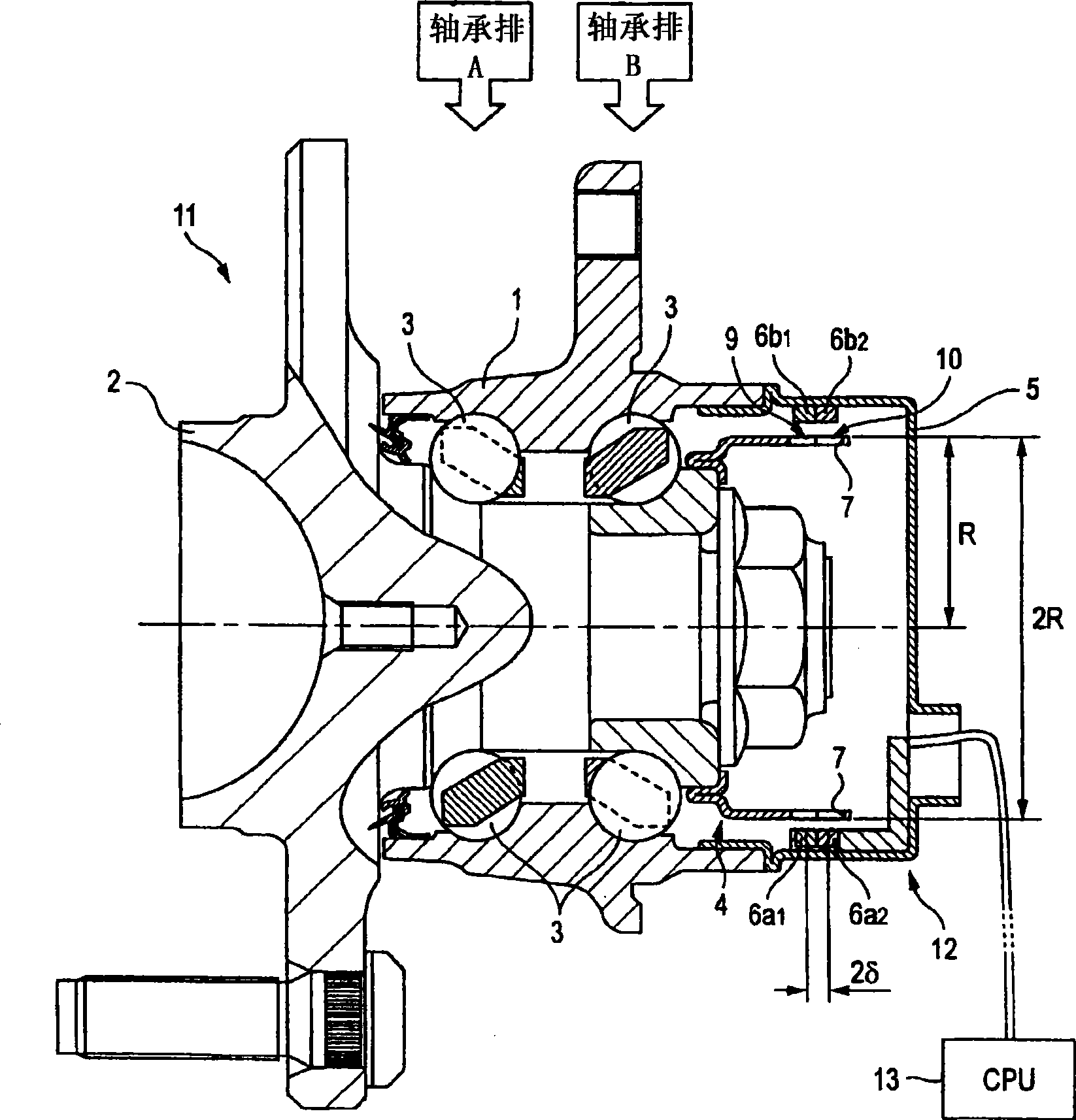
[0168] Figure 9 An embodiment according to the present invention is shown, corresponding to a second example of the sixth aspect of the present invention. This example has features on the detection surface of the encoder 4a. Since the structure and operation of other components are the same as the case according to the first example of this embodiment. Duplicate illustrations and descriptions thereof are omitted or simplified. Hereinafter, characteristic components of the present example will be mainly described.

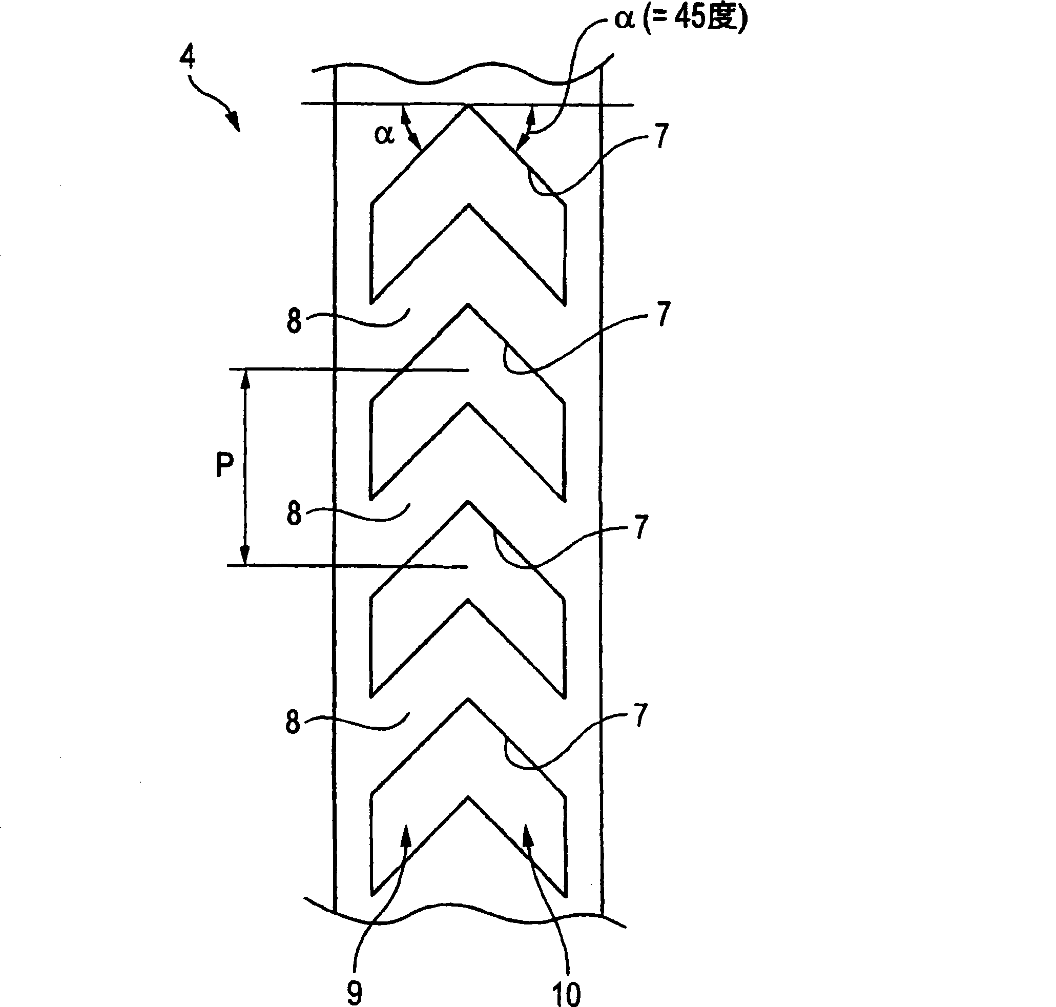
[0169] In the case of the present example, the plurality of through holes 7a and 7a constituting the first characteristic changing portion 9a and the plurality of through holes 7b and 7b constituting the second characteristic changing portion 10a are formed independently of each other on the detection surface of the encoder 4a superior. Furthermore, similarly to the case according to the first example of this embodiment, the boundary between the through holes 7...


PUM


Abstract

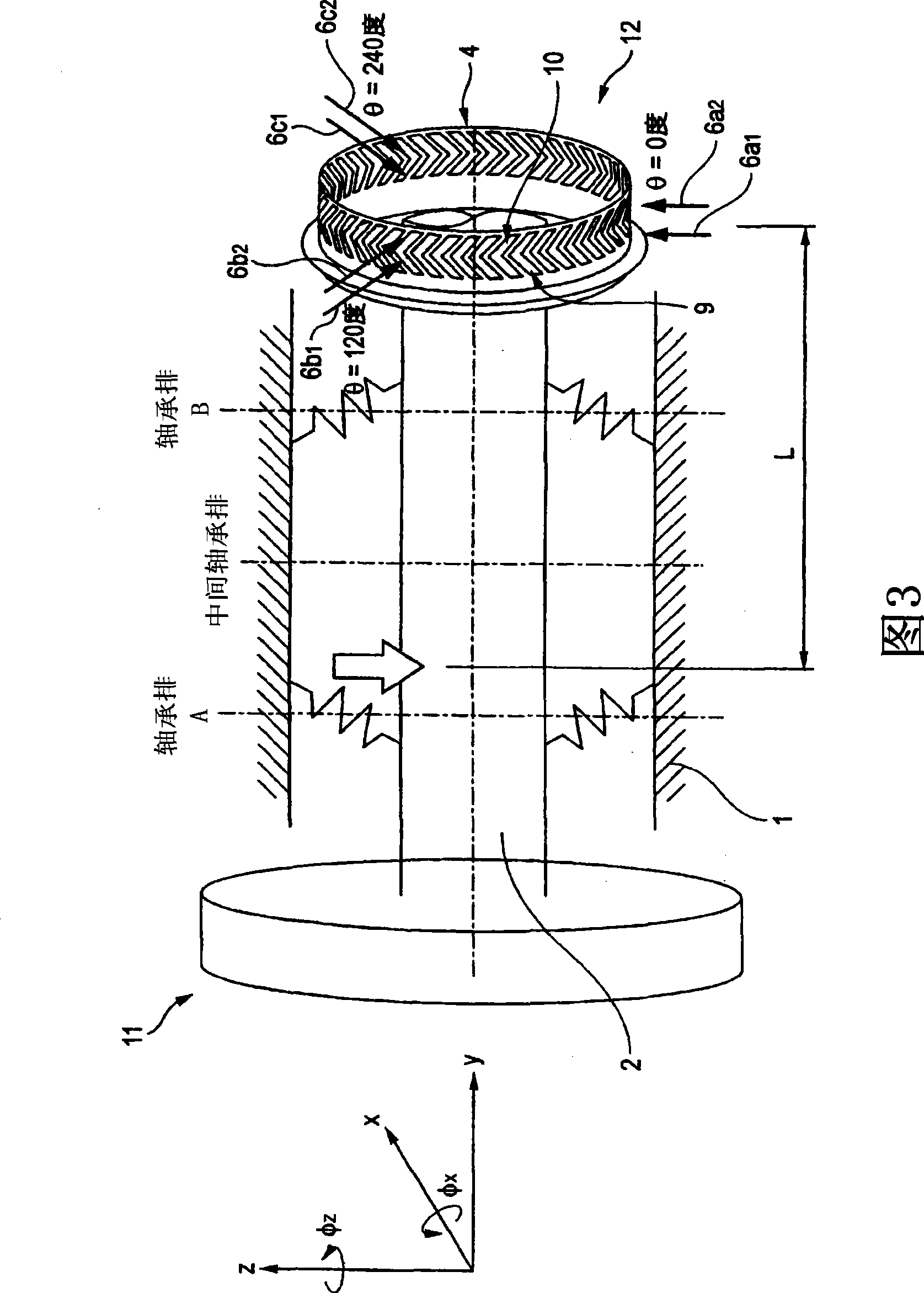
The outer circumference of an encoder (4) has its inner and outer half portions formed into first and second characteristic changing portions (9, 10), in which the directions of inclination of characteristic boundaries are different from each other. Three circumferential portions of those two characteristic changing portions (9, 10) are individually confronted by detecting units of pairs of sensors (6a1 (6b1, 6c1)) and (6a2 (6b2, 6c2)). Moreover, a not-shown functional unit is given a function to compute displacements (x, y, z) and inclinations (theta x, theta z) on the basis of the phase differences existing between the output signals of those individual sensors (6a1, 6a2, 6b1, 6b2, 6c1, 6c2).

Description

technical field [0001] The state measuring device for a rotating machine according to the present invention is used to measure the state between a stationary part and a rotating part constituting a rotating machine such as a rolling bearing unit, that is, a relative displacement between the two parts, or a state applied between the two parts. External forces (loads, moments) between various components. Furthermore, the resulting state is used to secure driving stability of a vehicle such as an automobile. Background technique [0002] Wheels of an automobile are rotatably supported to a suspension device through a rolling bearing unit such as a double row angular rolling bearing unit. In order to secure the driving stability of automobiles, vehicle driving stabilizing devices such as anti-lock braking system (ABS), traction control system (TCS), and electronic stability control system (ESC) as described in Non-Patent Document 1 have been used . In order to control these v...

Claims


Application Information

Patent Timeline
Patent Type & Authority Applications(China)
IPC IPC(8): G01L5/00B60B35/02F16C19/18F16C41/00G01D5/245
CPCF16C19/522F16C19/186B60B27/0094B60B27/0005B60B27/0068G01L5/0004G01D5/2451G01L5/0023F16C41/00F16C2326/02
Inventor 小野浩一郎土肥永生
Owner NSK LTD
Learn More