Photomultiplier and radiation sensor

A photomultiplier tube and radiation detection technology, which is applied in the direction of electron multiplier tubes, electrode devices with multiple dynodes, detailed information of electron multipliers, etc., can solve problems such as insufficient connections, and achieve high detection efficiency.

Active Publication Date: 2010-07-14
HAMAMATSU PHOTONICS KK
View PDF6 Cites 0 Cited by
  • Summary
  • Abstract
  • Description
  • Claims
  • Application Information

AI Technical Summary

Problems solved by technology

At this time, there are cases where stress is generated at the junction of the exhaust pipe and the vacuum vessel, resulting in insufficient connection.

Method used


Image

  • Photomultiplier and radiation sensor
  • Photomultiplier and radiation sensor
  • Photomultiplier and radiation sensor

Examples


Embodiment Construction

[0044] Hereinafter, embodiments of the present invention will be described with reference to the drawings.

[0045] Figure 1 to Figure 22 It is a diagram showing a radiation detection device including a photomultiplier tube according to an embodiment of the present invention. In each figure, the same code|symbol is attached|subjected to the substantially same part, and repeated description is abbreviate|omitted. In addition, in the following description, terms such as "upper" and "lower" are used for convenience based on the states shown in the drawings.

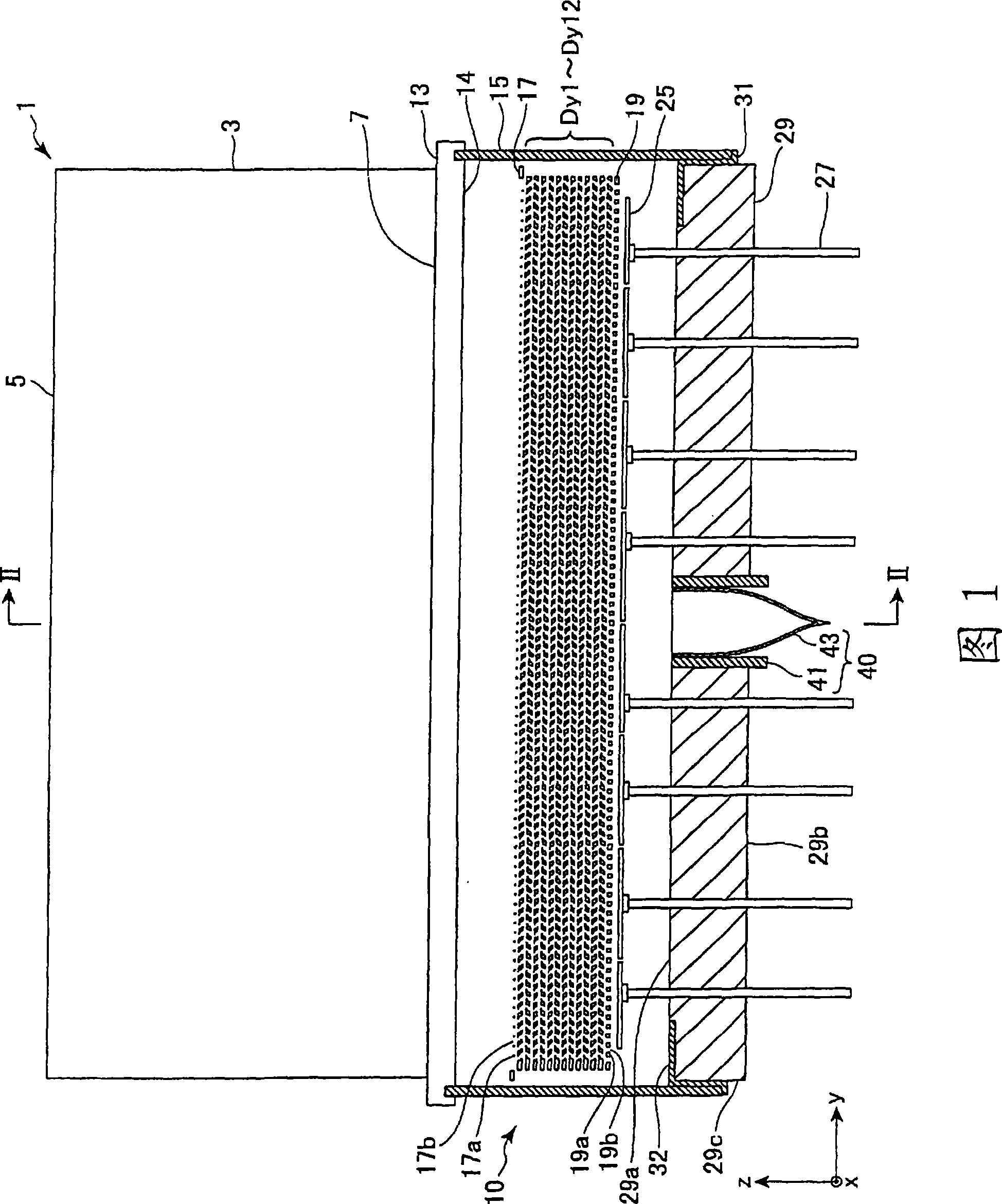
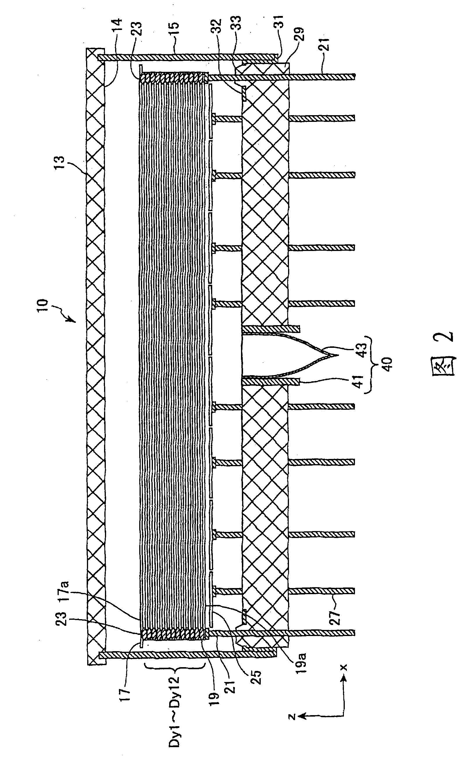
[0046] figure 1 is a schematic cross-sectional view of the radiation detection device 1 of the present embodiment, figure 2 is along figure 1 A schematic cross-sectional view of the photomultiplier tube 10 on the II-II plane of FIG. Such as figure 1 , figure 2 As shown, the radiation detection device 1 is a device that detects incident radiation and outputs it as a signal, and has: a scintillator (scintillator) 3 t...


PUM


Abstract

A vacuum vessel is configured by hermetically joining a faceplate (13) to one end of a side tube (15) and a stem (29) to the other end via a tubular member (31). A photocathode (14), a focusing electrode (17), dynodes (Dy1-Dy12), a drawing electrode (19), and anodes (25) are arranged within the vacuum vessel. At the center of the stem (29) an air discharging tube (40) is connected. The air discharging tube (40) includes an outer side tube (41) and an inner side tube (43), which are disposed coaxially and connected to each other at the stem (29) side. The outer side tube (41) has high adhesiveness with the stem (29) and the inner side tube (43) is thin and has small stress when being cut, thereby enabling the joint with the vacuum vessel not to be damaged when the air discharging tube (40)is sealed.

Description

technical field [0001] The present invention relates to a photomultiplier tube and a radiation detection device using the photomultiplier tube. Background technique [0002] Conventionally, there are known photomultiplier tubes in which electrons emitted from a photoelectric surface provided on one side of a vacuum vessel are amplified by a dynode and detected by an anode, and a large cone is used to detect the electrons. Shaped sealing glass forms a stem constituting the other end of the vacuum vessel, and a metal tip tube (metal chip) as a metal exhaust pipe hangs down from the center of the stem by welding (for example, refer to Patent Document 1). [0003] Also, there is an example in which the exhaust pipe is airtightly fitted and fixed on a disc-shaped stem metal plate arranged to surround the outer surface of the vacuum vessel of the stem constituting the other end of the vacuum vessel (for example, refer to Patent Document 2). [0004] Patent Document 1: Japanese P...

Claims


Application Information

Patent Timeline
Patent Type & Authority Patents(China)
IPC IPC(8): H01J43/28H01J43/22G01T1/20
CPCH01J43/22H01J43/28
Inventor 下井英树久嶋浩之
Owner HAMAMATSU PHOTONICS KK
Why Eureka
Try Eureka