Magnetic resonance imaging apparatus and analysis method for fat suppression effect in magnetic resonance imaging apparatus

一种磁共振成像、脂肪抑制的技术,应用在生物电信号测量、医药科学、诊断等方向,能够解决花费等问题

Inactive Publication Date: 2009-04-01
TOSHIBA MEDICAL SYST CORP
View PDF1 Cites 15 Cited by
  • Summary
  • Abstract
  • Description
  • Claims
  • Application Information

AI Technical Summary

Problems solved by technology

Therefore, in the case where the spatial unevenness of the large fat suppression effect appears in the image captured by a certain device, it is necessary to take measures (adjustment or parts replacement) that may be effective for various causes as described above. While confirming the improvement of the phenomenon, it takes a lot of labor

Method used


Image

  • Magnetic resonance imaging apparatus and analysis method for fat suppression effect in magnetic resonance imaging apparatus
  • Magnetic resonance imaging apparatus and analysis method for fat suppression effect in magnetic resonance imaging apparatus
  • Magnetic resonance imaging apparatus and analysis method for fat suppression effect in magnetic resonance imaging apparatus

Examples


Embodiment Construction

[0027] Hereinafter, embodiments of the present invention will be described with reference to the drawings.

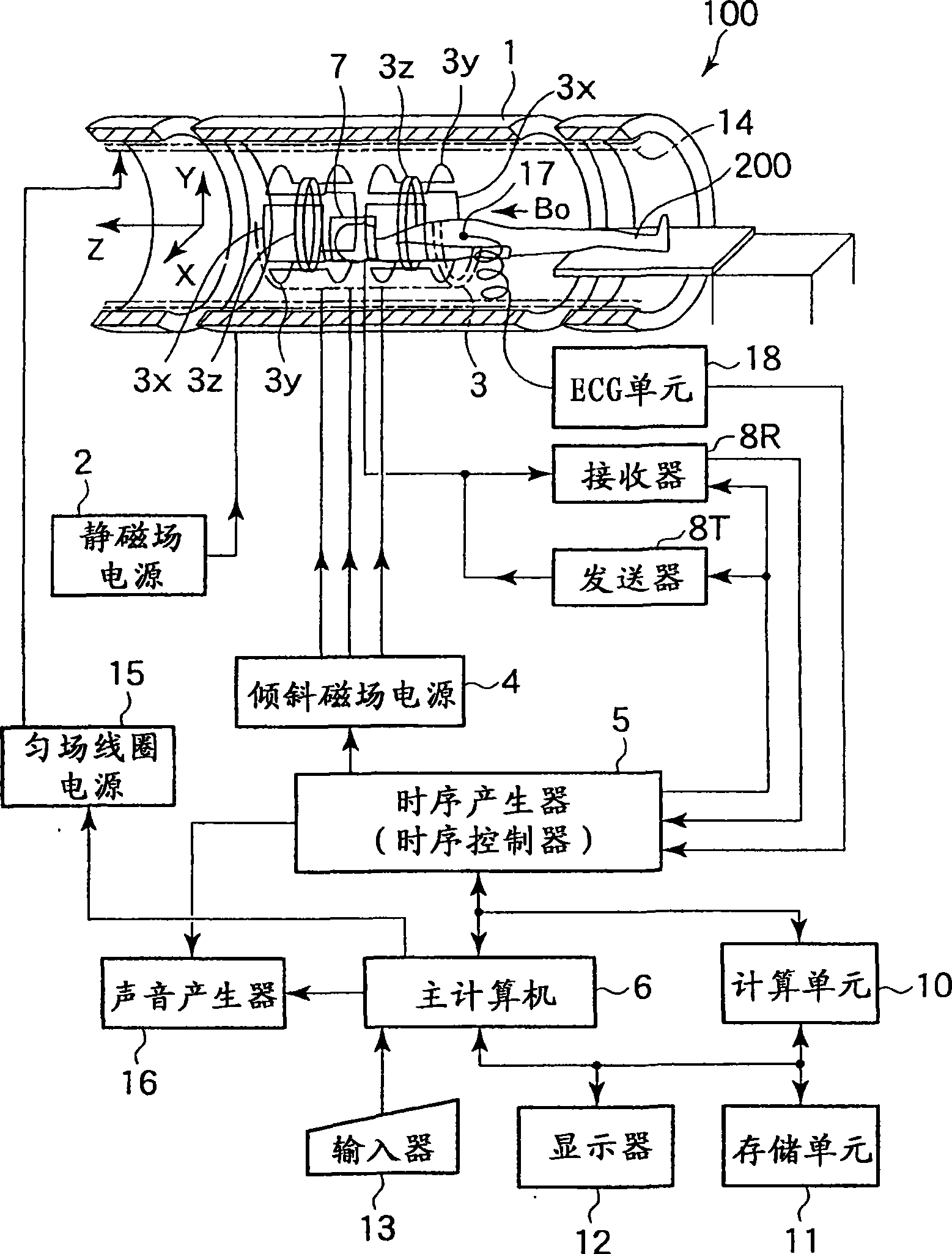
[0028] figure 1 It is a diagram showing the configuration of a magnetic resonance imaging apparatus (hereinafter referred to as an MRI apparatus) 100 of this embodiment.

[0029] The MRI apparatus 100 is equipped with: a bed unit for carrying the subject 200; a static magnetic field generating unit for generating a static magnetic field; a gradient magnetic field generating unit for adding position information to the static magnetic field; a transmitting and receiving unit for transmitting and receiving high-frequency signals; The overall control of the system and the control computing part of the image reconstruction. In addition, as constituent elements of these components, the MRI apparatus 100 has a magnet 1, a static magnetic field power supply 2, a gradient magnetic field coil unit 3, a gradient magnetic field power supply 4, a timing generator (sequence controll...


PUM


Abstract

A magnetic resonance imaging apparatus includes an imaging unit which performs imaging more than once with respect to an imaging target while changing a central frequency of a fat suppression pulse, a generation unit which generates a plurality of images based on magnetic resonance signals obtained by imaging performed more than once, and a calculation unit which calculates factor information of spatial inhomogeneity of a fat suppression effect based on the plurality of images.

Description

technical field [0001] The present invention relates to a magnetic resonance imaging device that suppresses fat signals by applying fat suppression pulses and a method for analyzing the fat suppression effect of the magnetic resonance imaging device. Background technique [0002] As a fat suppression method for magnetic resonance imaging, a chemical shift selective (CHESS) method, a spatial-spectral excitation pulse method, and the like are known. [0003] In any of these fat-suppressing methods, spatial inhomogeneity of the fat-suppressing effect occurs. As a method for improving the spatial unevenness of the fat suppression effect, there is so-called current shimming. In current filling, the spatial distribution of the magnetic field is measured before imaging. Then, at the time of imaging, considering the spatial distribution of the magnetic field measured before imaging, a constant correction current is passed through the gradient magnetic field coil and the magnetic f...

Claims


Application Information

Patent Timeline
Patent Type & Authority Applications(China)
IPC IPC(8): A61B5/055
CPCA61B5/7285A61B5/055A61B5/0402A61B5/318
Inventor 金泽仁
Owner TOSHIBA MEDICAL SYST CORP
Why Eureka
Try Eureka