

Welding gun gripping swing mechanism
A technology of swing mechanism and driving mechanism, applied in welding equipment, welding equipment, arc welding equipment, etc., can solve the problems of low efficiency, high labor intensity, and difficult quality assurance.
- Summary
- Abstract
- Description
- Claims
- Application Information
AI Technical Summary
Problems solved by technology
Method used
Image

Examples
Embodiment Construction
[0015] Hereinafter, the present invention will be described in more detail with examples in conjunction with the accompanying drawings:
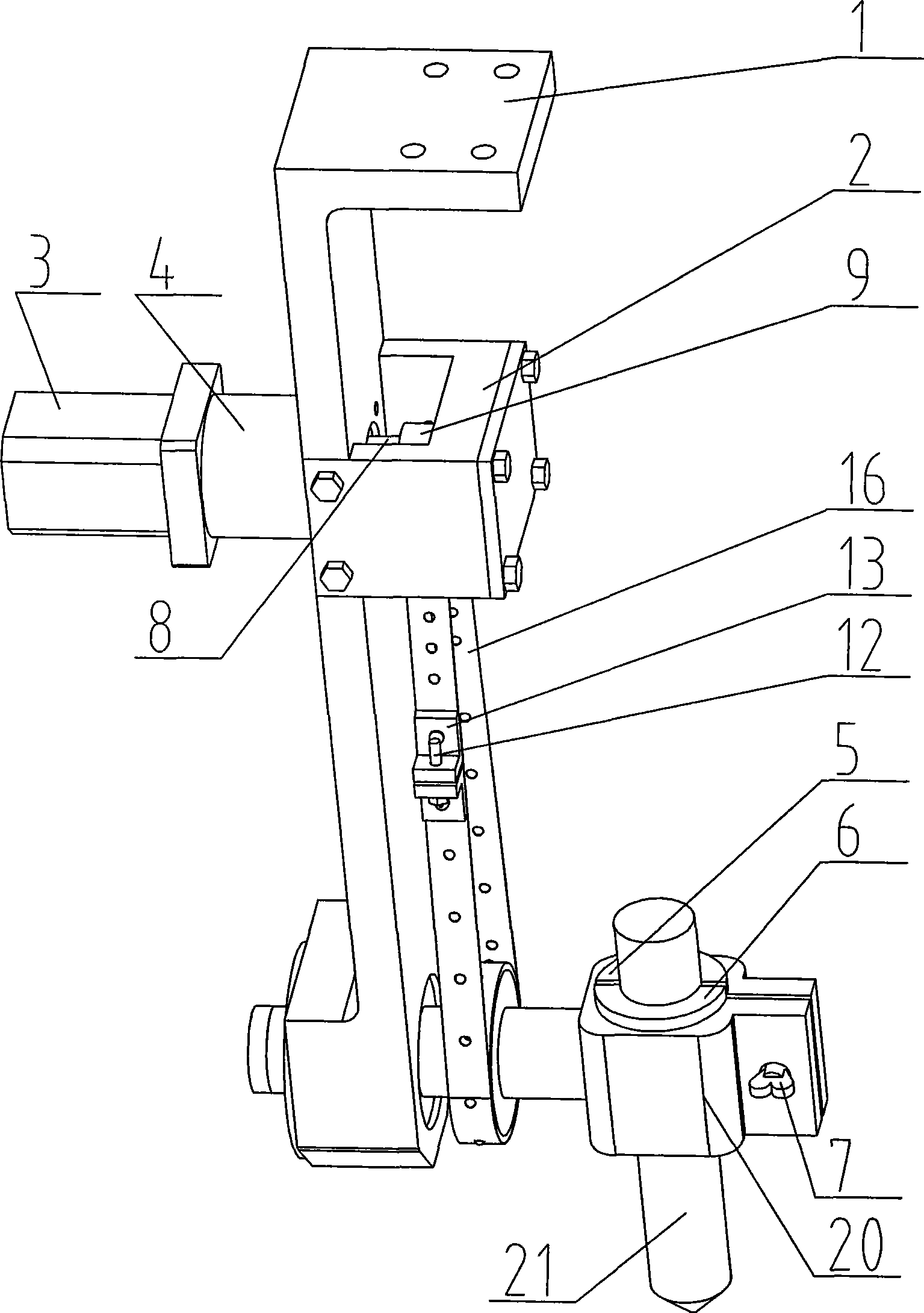
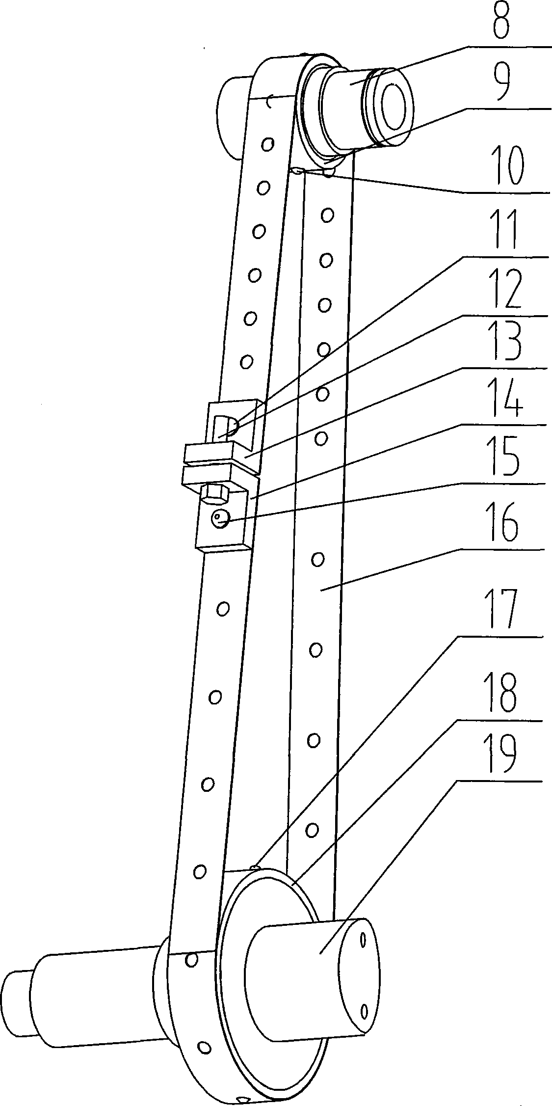
[0016] this invention figure 1 with figure 2 The symbol of each part represents: 1. Swing frame body, 2. Active shaft bracket, 3. Motor, 4. Reducer, 5, 6. Insulation sleeve, 7. Ingot screw, 8. Active shaft, 9. Active shaft Ball sleeve, 10, 17. Ball, 11, 15. Rivet, 12. Screw, 13, 14. Elastic connection block, 16. Ring steel belt, 18. Driven shaft bead sleeve, 19. Driven shaft, 20. Clamp Holder, 21. Welding gun.
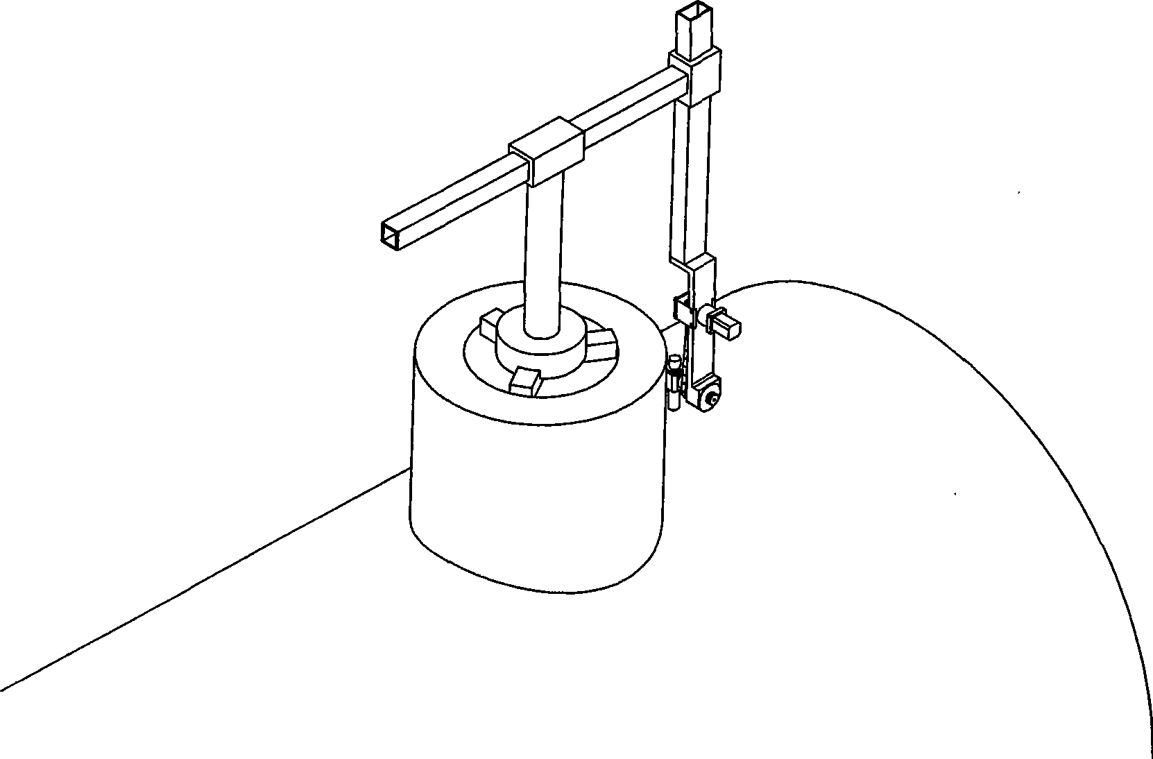
[0017] Such as figure 1 with figure 2 As shown, the present invention is a tube-type welding robot end joint or swing joint for pipe welding. It includes a driving shaft 8 and a driven shaft 19 mounted on the swing frame body 1. One end of the driving shaft 8 is connected to the motor 3 Connected to the driving mechanism formed by the reducer 4, the clamper 20 is fixed on the driven shaft 19, the driving shaft 8 and the driven shaft ...
PUM
 Abstract
Description
Claims
Application Information