
CT imaging method of multitime scanning mode

A multi-scanning and CT imaging technology, applied in the field of X-ray CT, can solve the problems of low resolution of reconstructed images, slow image reconstruction speed, increased calculation amount, etc.

Inactive Publication Date: 2009-04-01
CAPITAL NORMAL UNIVERSITY
View PDF5 Cites 20 Cited by
  • Summary
  • Abstract
  • Description
  • Claims
  • Application Information

AI Technical Summary

Problems solved by technology

As we all know, data rearrangement not only greatly increases the amount of calculation, but also reduces the resolution of the reconstructed image. Therefore, both the second-generation scanning method and the rotation plus translation scanning method have the problems of large data calculation, slow image reconstruction speed, and low resolution of the reconstructed image. shortcoming

Method used

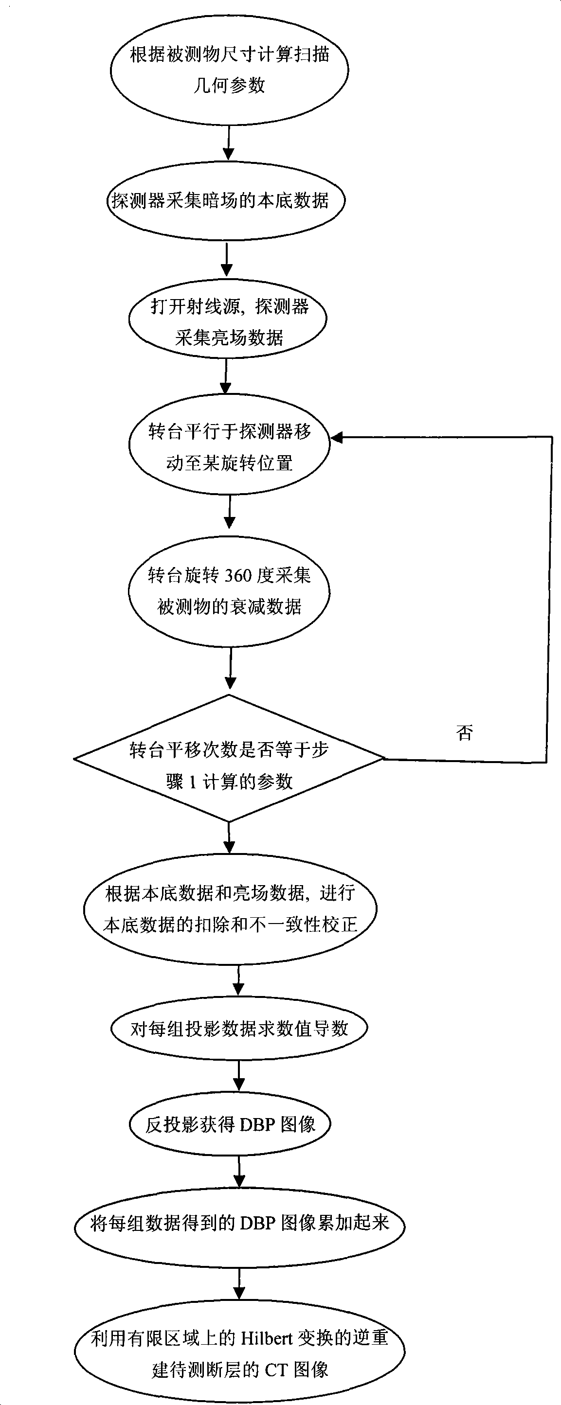
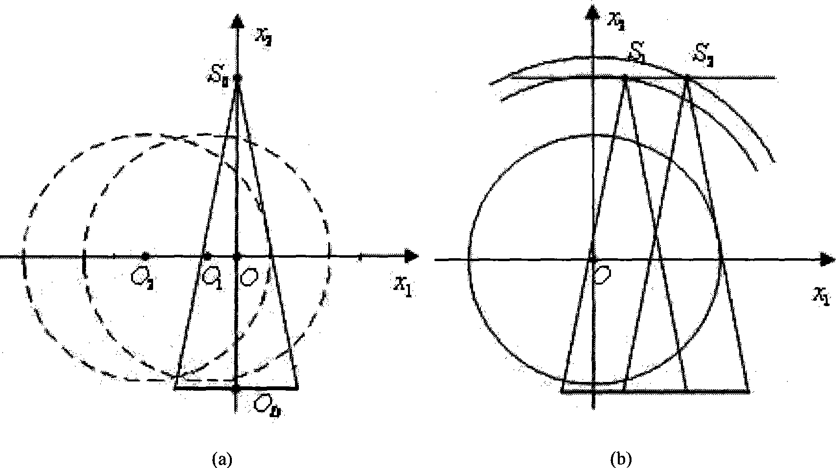

Image

  • CT imaging method of multitime scanning mode
  • CT imaging method of multitime scanning mode
  • CT imaging method of multitime scanning mode

Examples


Embodiment Construction

[0038] In the CT imaging method of multi-scanning mode, the specific calculation method of the distance and the number of times that the center of the turntable needs to be translated in step (1) is: figure 2 (a), R O is the ray source S 0 Distance from the center of rotation O of the turntable, R D is the ray source S 0 with detector center O D The distance between , l is the length of the detector, so the scanning field radius of a single scan Rfov = R O l / 4 R D 2 + l 2 , Assuming that the maximum radius of the object to be measured is ObjectR, the number of times the turntable needs to be translated is NumTran ≥ [ ObjectR · l ...


PUM


Abstract

The invention relates to a CT imaging method which is based on multiple scanning and used for CT imaging, namely, super-visual field CT imaging, when the scanning visual field of CT equipment can not cover an object to be detected. The method comprises the following steps: a projection data set is obtained by multiple scanning and collection and the CT image of the object to be scanned is obtained by that a scanning reconstruction algorithm is operated to process the projection data set. The invention is characterized in that when the object to be detected is scanned, the area covered by each scanning is allowed to have overlapped parts and the scanning reconstruction algorithm used for processing the projection data set does not need to rearrange the data. The invention has the main advantages that the size of the object to be detected is not limited by the CT scanning visual field, the scanning mode is flexible; as the reconstruction algorithm does not need to rearrange the data, interpolation calculation needed by the rearrangement and the degrading of the reconstructed image caused by the rearrangement are avoided, therefore, the reconstruction speed is fast and the resolution of the reconstructed image is high.

Description

technical field [0001] The invention belongs to the technical field of X-ray CT, and is used for CT imaging when the scanning field of CT equipment cannot cover a detected object (that is, super-field CT imaging). Background technique [0002] In industrial non-destructive testing, the problem of using short line array detectors to detect large-sized objects is often encountered. For the scanning problem that the large-sized measured object cannot be completely covered by the scanning field of view, the traditional solution is to use the second-generation scanning method, that is, the scanning method of translation and rotation, but it requires a turning area when collecting edge data of the measured object. It is close to the circumscribed field of view, which not only wastes the field of view and rays, but also increases the scanning time and the cost of data storage and transmission. [0003] Aiming at the problems existing in the second-generation scanning method, a sca...

Claims


Application Information

Patent Timeline
IPC IPC(8): G01N23/04G03B42/02H05G1/00G06F19/00
Inventor 张朋张慧滔陈明陈德峰
Owner CAPITAL NORMAL UNIVERSITY
Learn More