Optical fiber laser acceleration sensor

A technology of acceleration sensor and fiber laser, which is applied in the direction of acceleration measurement using inertial force, can solve the problems of limiting the sensitivity of the sensor, the deflection of the cantilever beam cannot be too large, and the sensor volume is large, so as to achieve the effect of volume reduction

Inactive Publication Date: 2009-04-01
INST OF SEMICONDUCTORS - CHINESE ACAD OF SCI
View PDF0 Cites 16 Cited by
  • Summary
  • Abstract
  • Description
  • Claims
  • Application Information

AI Technical Summary

Problems solved by technology

In order to maintain a linear relationship between the acceleration and the output of the sensor in this technical solution, the deflection of the cantilever beam cannot be too large, thereby limiting the sensitivity of the sensor. At the same time, due to the structure of the cantilever beam, the volume of the sensor is too large

Method used


Image

  • Optical fiber laser acceleration sensor
  • Optical fiber laser acceleration sensor
  • Optical fiber laser acceleration sensor

Examples


Embodiment Construction

[0032] In order to make the object, technical solution and advantages of the present invention clearer, the present invention will be described in further detail below in conjunction with specific embodiments and with reference to the accompanying drawings.

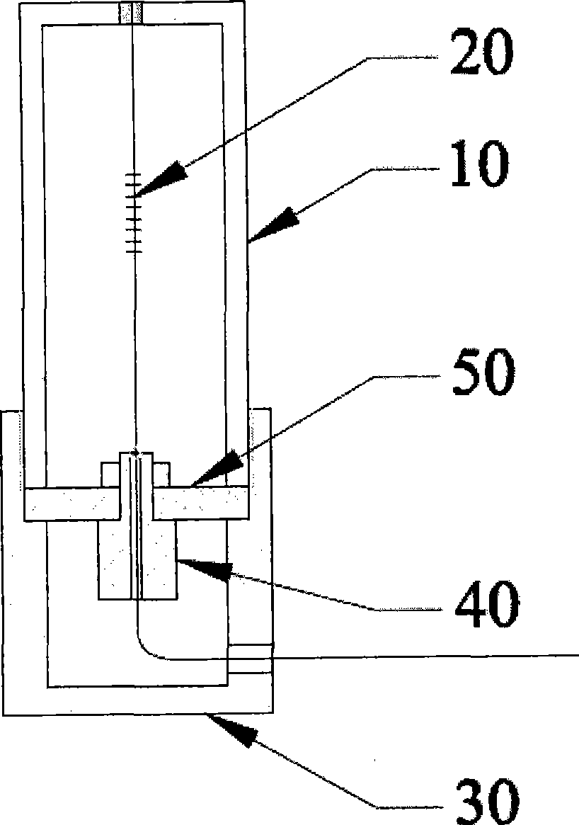
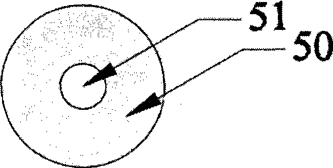
[0033] like figure 1 as shown, figure 1 It is a structural schematic diagram of the fiber laser acceleration sensor provided by the present invention, the fiber laser acceleration sensor includes a support cylinder 10 , an end cover 30 , an elastic diaphragm structure 50 , a mass 40 and a fiber laser 20 .

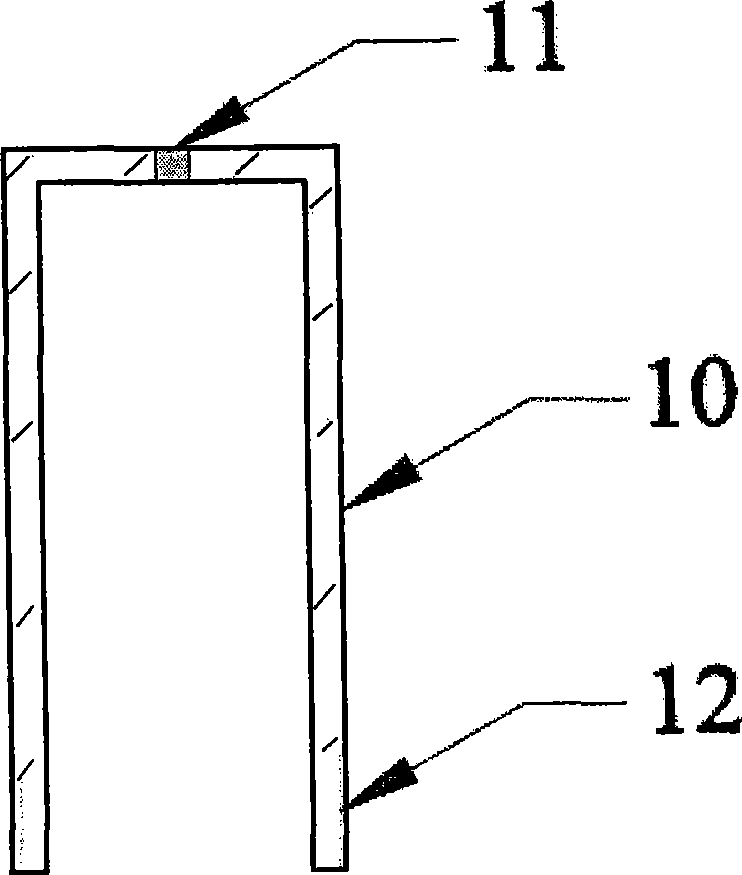
[0034] Figure 2 to Figure 5 As shown, the support cylinder 10 serves as the main body of the fiber laser acceleration sensor, with an opening at one end and a first small hole 11 at the center of the other end for fixing the fiber laser 20 . The end cap 30 is installed on the open end of the support cylinder 10 for fixing and protecting the internal structure of the fiber laser acceleration sensor and leading out th...


PUM


Abstract

The invention discloses an optical fiber laser acceleration sensor, comprising a support cylinder which is the main part of the optical fiber laser acceleration sensor and one end of which is provided with an opening while the other end of which is provided with a first pore used for fixing a fiber laser, an end housing which is installed on the opening end of the support cylinder and used for fixing and protecting the internal structure of the optical fiber laser acceleration sensor, as well as leading out the fiber pigtails of the fiber laser, an elastic membrane structure which is fixed between the opening end and the end housing of the support cylinder and used for producing deformation under the action of acceleration, a mass block which is mounted in the center of the elastic membrane structure and used for enhancing the deformation of the elastic membrane structure generated under the action of acceleration, and the fiber laser which penetrates through the elastic membrane structure and the mass block and is used for measuring the acceleration. The invention increases the measuring sensitivity of the fiber laser acceleration sensor, reduces the bulk of the fiber laser acceleration sensor, and improves the technical uniformity.

Description

technical field [0001] The invention relates to the technical field of optical fiber sensors, in particular to a novel ultrathin optical fiber laser acceleration sensor. Background technique [0002] Compared with the corresponding conventional sensors, fiber optic sensors have obvious advantages in terms of sensitivity, dynamic range, and reliability. They are particularly prominent in the fields of national defense and military applications, and are listed as key national defense technologies by many countries. [0003] The fiber optic acceleration sensor is an instrument that detects the vibration, acceleration and other signals of the surrounding environment by using the light transmission characteristics of the optical fiber and various modulation effects generated by its interaction with the surrounding environment. Compared with traditional piezoelectric sensors, it has the following main advantages: wide frequency band, high sound pressure sensitivity, no electromagn...

Claims


Application Information

Patent Timeline
Patent Type & Authority Applications(China)
IPC IPC(8): G01P15/03
Inventor 张文涛李芳刘育梁
Owner INST OF SEMICONDUCTORS - CHINESE ACAD OF SCI
Why Eureka
Try Eureka