Deep draw mould without flange edge die plate

A technology without flange and die, applied in the field of deep drawing dies, can solve the problems of reducing tensile stress, high cost, limited use occasions, etc., to improve the ultimate deep drawing height, improve forming performance, reduce manufacturing costs and energy consumption Effect

Inactive Publication Date: 2009-04-08
ZHEJIANG UNIVERSITY OF SCIENCE AND TECHNOLOGY
View PDF0 Cites 14 Cited by
  • Summary
  • Abstract
  • Description
  • Claims
  • Application Information

AI Technical Summary

Problems solved by technology

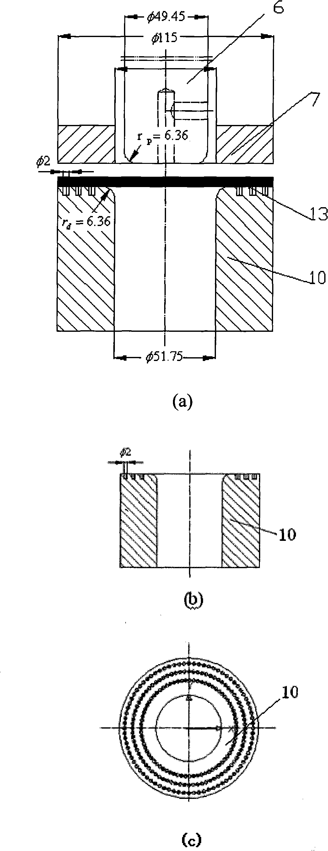
[0003] At present, there are the following improved steel mold structures: ① Dense process small blind holes are drawn on the upper plane of the die, and these process small blind holes are used to store lubricating oil and reduce the contact area with the blank during drawing. Thereby, the tensile stress is reduced, the cracking in the sheet metal forming is suppressed to a certain extent, and the limit ability of the sheet metal forming is improved, but this process structure is time-consuming and costly, and it is difficult to popularize it in actual production.
[0004] ②Conical surface die and conical rigid blank holder mold, the process method of processing the contact surface of the die with the blank and the surface of the blank holder with the blank into a conical surface for deep drawing, this method can to a certain extent Increase the limit drawing height without cracking and wrinkling, but it has a certain effect only when the sheet is relatively thick (or relatively thick), and the drawing has a large inner fillet radius. Use limited occasions

Method used


Image

  • Deep draw mould without flange edge die plate
  • Deep draw mould without flange edge die plate
  • Deep draw mould without flange edge die plate

Examples


Embodiment Construction

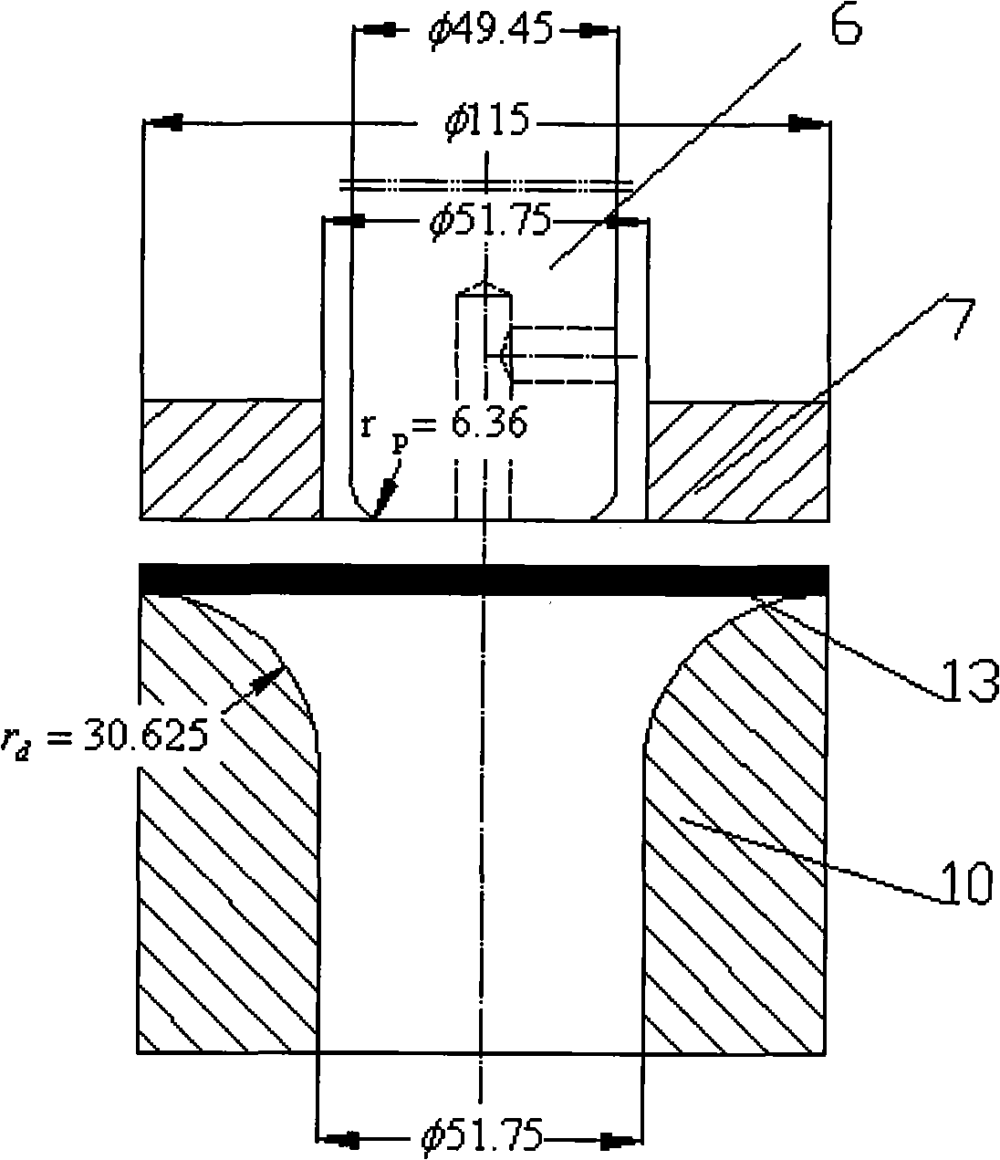
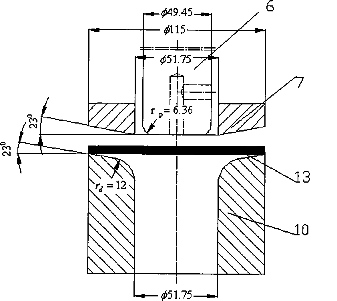
[0034] On the basis of the structure characteristics of the existing dies, a deep drawing die without a flanged die is proposed. The shape and size of the die of this kind of mold are consistent with the expanded shape and size of the drawn part, and the radius of the fillet of the die is equal to the radial length from the edge of the die to the cavity and transitions along the circumference. This mold structure has the following characteristics: (1) During deep drawing, the time for the rigid blank holder to act on the outer edge of the blank is relatively short, but since it is pressed on the arc surface at the beginning, and the arc surface is lowered radially Therefore, the thickening of the sheet metal will not exceed the initial plane of the blank. When the initial blank holder force takes a large value, the outer edge of the blank will not be warped; (2) When the blank holder is completed, the blank will Therefore, the increase of radial tensile stress used to overcome...


PUM

PropertyMeasurementUnit
thicknessaaaaaaaaaa
elastic modulusaaaaaaaaaa
Poisson's ratioaaaaaaaaaa

Abstract

The invention discloses a deep drawing die of a non-flanged edge concave die. The corner radius of a concave die in a drawing die is equal to the radial length from the edge to a die cavity of the concave die and transit along the circumference; the lower end of an upper die plate is provided with a convex die which is arranged on a convex die fixing plate and in a pressing-material ring hole; the convex die fixing plate is in threaded connection with the upper die plate; the upper die plate is provided with more than three through holes provided with steps, in which rejected material bolts are inserted; the rejected material bolts, which are extended out of the lower end surface of the upper die plate, are orderly arranged in a spring; the end parts of the rejected material bolts are in threaded connection with a pressing-material ring; the non-flanged edge concave die is arranged on the center part of the upper end surface of the lower die plate; the center part of the non-flanged edge concave die is provided with a concave die cushion; and a head part spring is pressed against the lower end surface of the concave die cushion. The die can improve the forming performance of sheet materials, compared with the conical surface concave die, the conical surface rigid clamping ring die and the drawing die of which the upper surface of the concave die is closely punched with technological blind holes, the die has the advantages of improving the deepest drawing depth of a drawing piece without cracking, replacing multiple drawing by one-time drawing, and reducing cost and energy consumption.

Description

technical field [0001] The invention relates to equipment for forming sheet metal, in particular to a deep drawing die without a flanged concave die Background technique [0002] The research and development of new technologies to improve the process structure of steel molds, avoid or effectively suppress wrinkling and cracking in sheet metal forming, and improve the limit capacity of sheet metal forming has always been a hot topic in the field of sheet metal stamping at home and abroad. [0003] At present, there are the following improved steel mold structures: ① Dense process small blind holes are drawn on the upper plane of the die, and these process small blind holes are used to store lubricating oil and reduce the contact area with the blank during drawing. Thereby, the tensile stress is reduced, the cracking in the forming of the sheet is suppressed to a certain extent, and the limit ability of the sheet forming is improved. However, the processing of this process str...

Claims


Application Information

Patent Timeline
Patent Type & Authority Applications(China)
IPC IPC(8): B21D37/10B21D22/20
Inventor 施于庆
Owner ZHEJIANG UNIVERSITY OF SCIENCE AND TECHNOLOGY
Why Eureka
Try Eureka