
Regulating device, laser processing device, regulating method and program

A technology for adjusting devices and adjusting parts, which is applied in the direction of measuring devices, laser welding equipment, and optical devices, etc. It can solve the problems of undescribed rotation deviation, magnification or reduction scale transformation, shape distortion, etc., and achieve the effect of efficient calibration

Inactive Publication Date: 2009-04-08
OLYMPUS CORP
View PDF3 Cites 23 Cited by
  • Summary
  • Abstract
  • Description
  • Claims
  • Application Information

AI Technical Summary

Problems solved by technology

[0009] However, Patent Document 1 only describes the adjustment of the position deviation in the X direction or the Y direction, and does not describe the rotation deviation, scale transformation such as enlargement or reduction, and shape distortion.

Method used


Image

  • Regulating device, laser processing device, regulating method and program
  • Regulating device, laser processing device, regulating method and program
  • Regulating device, laser processing device, regulating method and program

Examples


no. 8 Embodiment approach

[0362] The eighth embodiment adopts the following mathematical model.

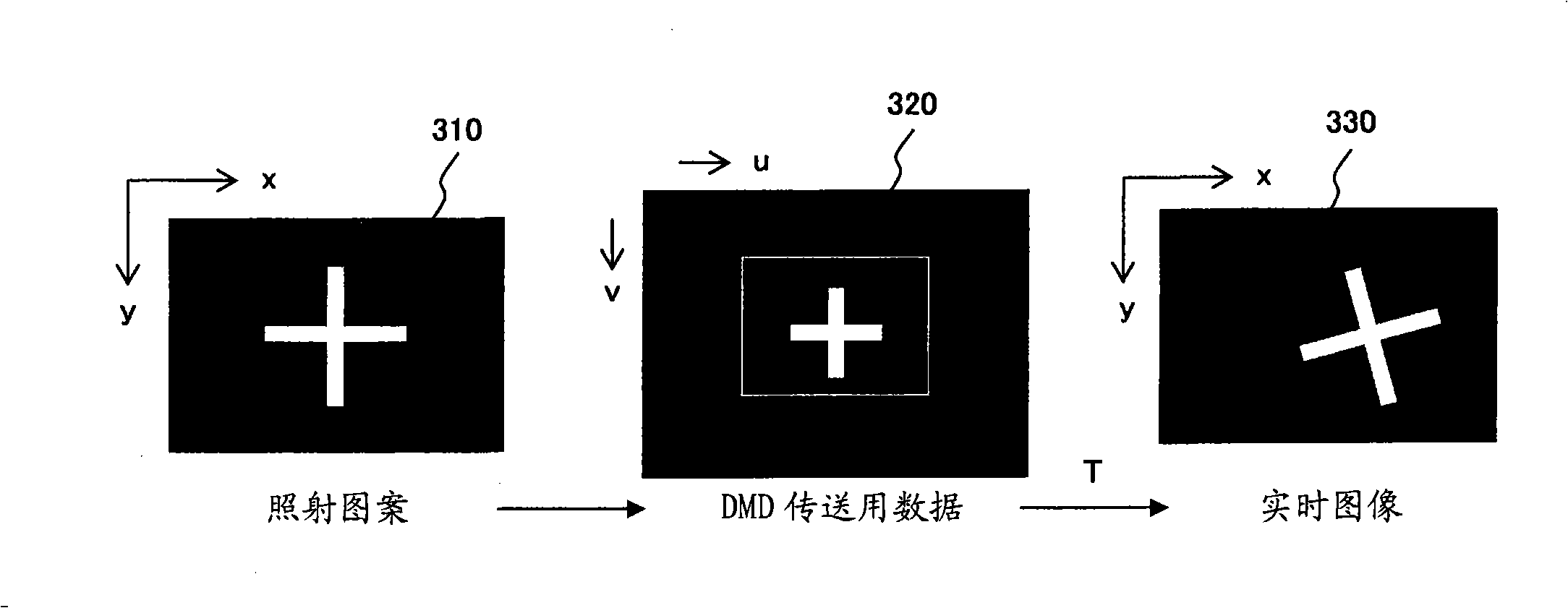
[0363] • The transformation from the input pattern to the output pattern in the state where the LED light source 116 is selected as the light source is an affine transformation.

[0364] ● This transformation is represented by the transformation matrix T of the expression (2).

[0365] There is a difference between the first output pattern corresponding to a certain input pattern when the LED light source 116 is selected as the light source, and the second output pattern corresponding to the same input pattern when the laser oscillator 103 is selected as the light source . This bias is also modeled by an affine transformation.

[0366] ●The parameter indicating the deviation between the first and second output patterns is expressed by the transformation matrix R shown in the formula (36) having the same form as the transformation matrix T. That is, the first output pattern is transformed into the second...


PUM


Abstract

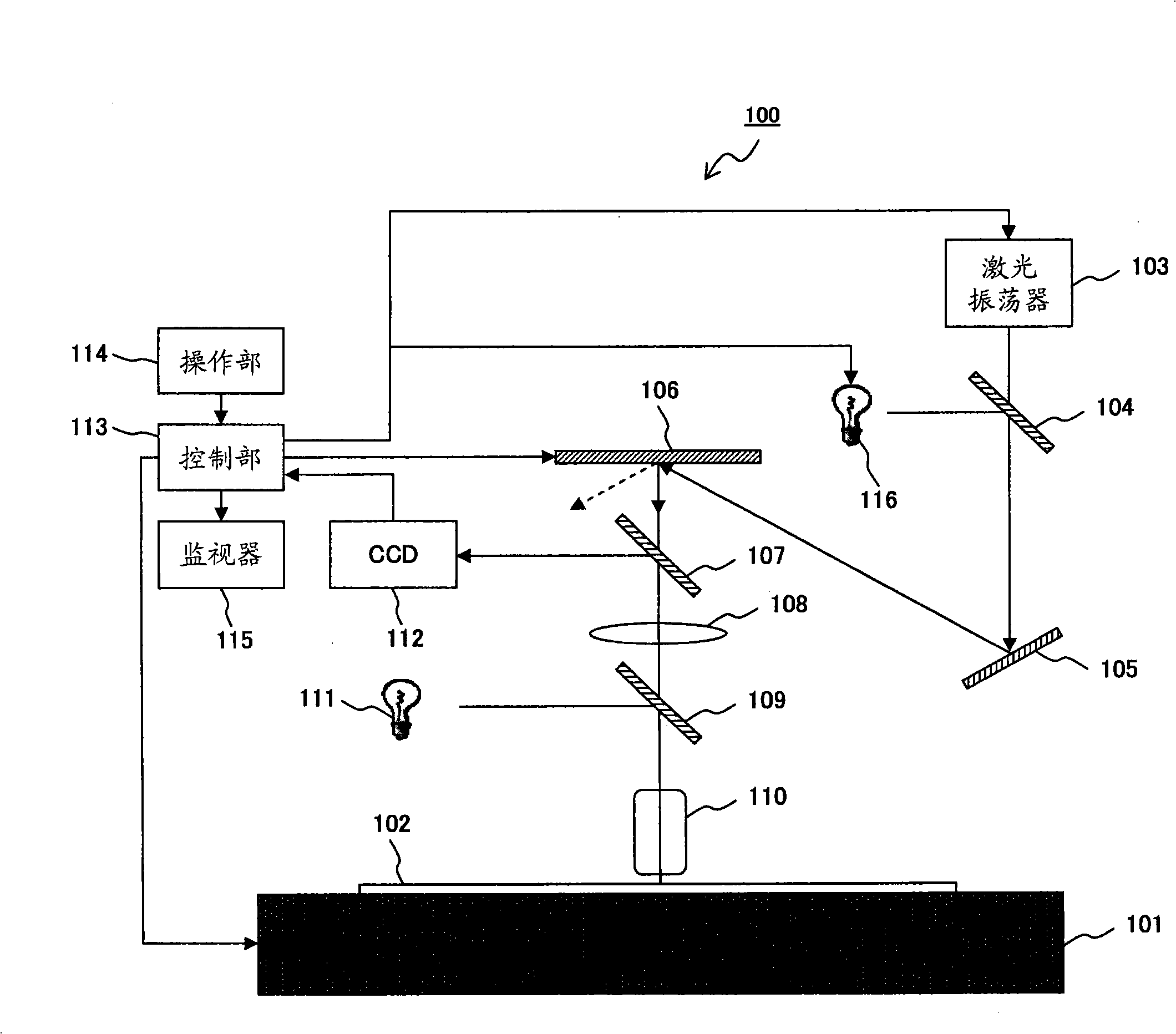
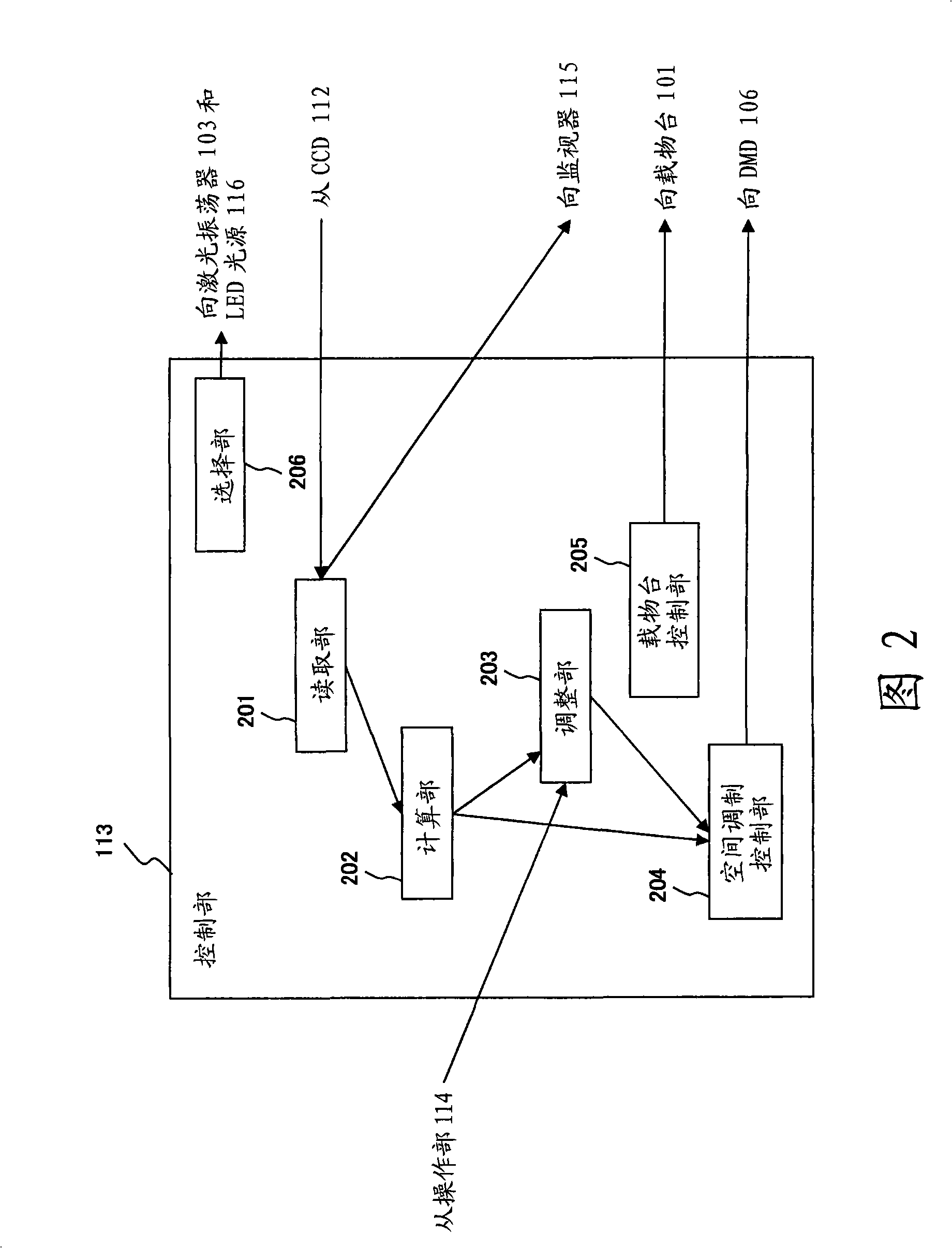
The invention provides an adjusting apparatus, laser processing device, adjustment method and adjustment procedures, which can effectively adjust the irradiation of lights after space modulation. When a control section (113) appoints a calibration pattern to the DMD (106), the LED light from an LED light source (116), after space modulation through the DMD (106), is irradiated onto an object to be processed (102). A CCD camera (112) shoots the object to be processed (102). The control section (113) reads the shot image, to calculate the transformation parameter of converting the calibration pattern into output pattern which is produced on the image correspondingly to the calibration pattern. When irradiation patterns appointed by an operation section (114) or the like, are irradiated onto an object to be processed (102) after pace modulation to the laser from an optical maser oscillator (103) through the DMD (106), the control section (113) modulates the laser irradiation based on transformation parameters.

Description

technical field [0001] The present invention relates to a technique for adjusting irradiation of light spatially modulated by a spatial modulation element. Background technique [0002] Conventionally, a laser processing device that processes a workpiece by irradiating a laser beam to the workpiece has been used. There are types such as sketching of characters or pictures, exposure, and repair (correction; repair) in the manufacturing process of the substrate during processing. In addition, the substrate also includes a flat panel display (FPD: Flat Panel Display) such as a liquid crystal display (LCD: Liquid Crystal Display), a plasma display panel (PDP: Plasma Display Panel), a semiconductor wafer (wafer), a laminated printed circuit board (multilayer printed circuit board) ) and other types. [0003] Such a laser processing apparatus is provided with a mechanism for irradiating laser light in a predetermined position, direction, and shape. Conventionally, a slit or the...

Claims


Application Information

Patent Timeline
Patent Type & Authority Applications(China)
IPC IPC(8): G02B26/08B23K26/00B23K26/073B23K26/02B23K26/04B23K26/064
CPCB23K26/032B23K26/0643B23K26/0648B23K26/044G01B11/14G01B11/164G03G2215/0402
Inventor 山崎隆一
Owner OLYMPUS CORP
Learn More