Electronic functional card and card connecting device

A card connection and function technology, which is applied to the components, connections, coupling devices, etc. of the connection device, and can solve the problems of difficult to form a small card connection device, complex structure, etc.

Inactive Publication Date: 2009-04-08
ALPS ALPINE CO LTD
View PDF3 Cites 7 Cited by
  • Summary
  • Abstract
  • Description
  • Claims
  • Application Information

AI Technical Summary

Problems solved by technology

However, in order to be able to install cards with different functions and different shapes on a common card connection device, it is unavoidable to arrange complex structures such as multiple connection terminals inside the card connection device.
Moreover, it is necessary to separately install a holding mechanism corresponding to each type of card in the card connecting device, which makes it difficult to form a small card connecting device.

Method used


Image

  • Electronic functional card and card connecting device
  • Electronic functional card and card connecting device
  • Electronic functional card and card connecting device

Examples


Embodiment Construction

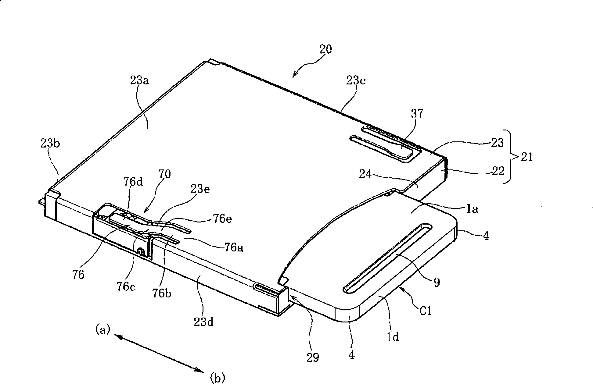
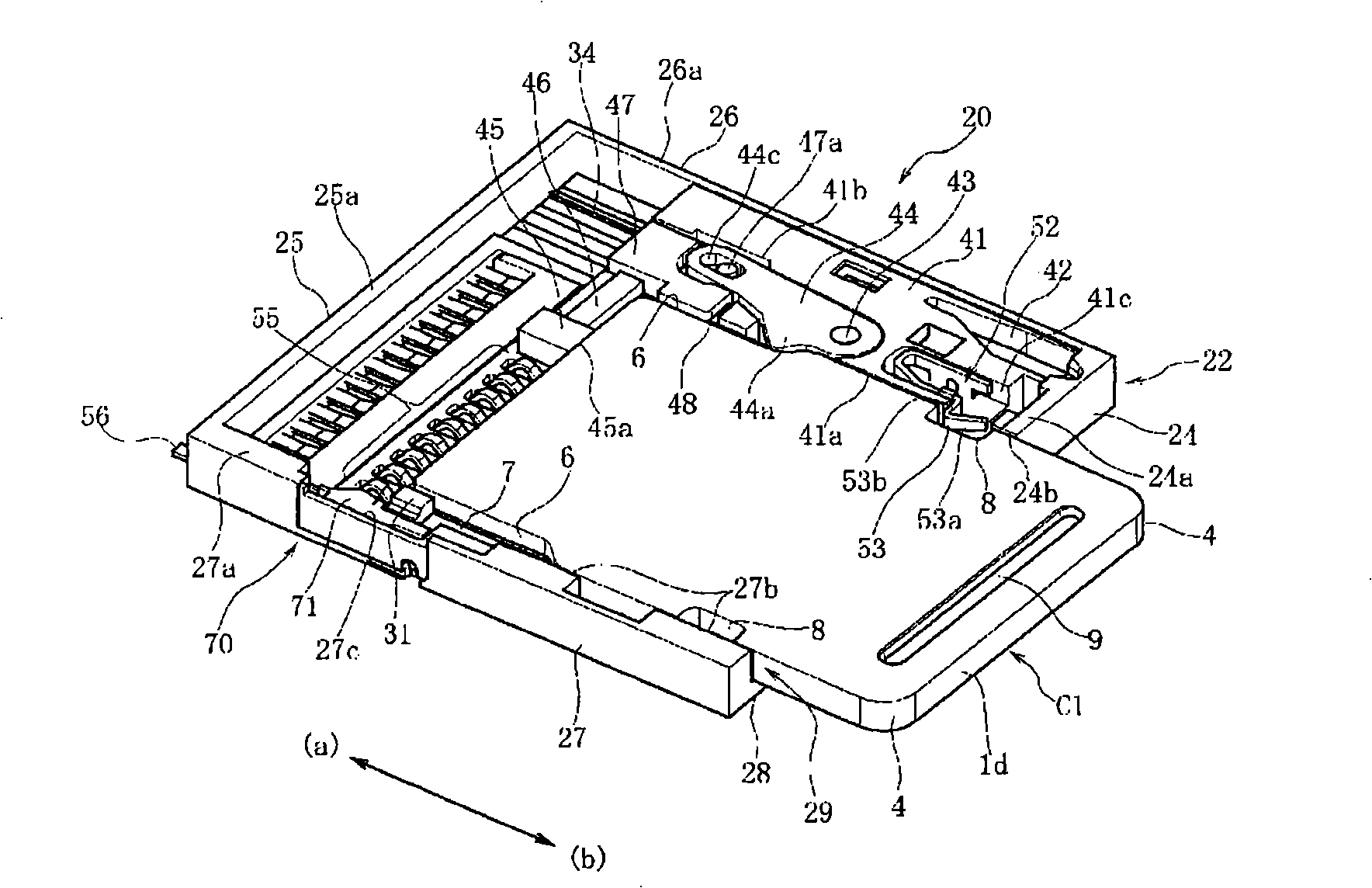
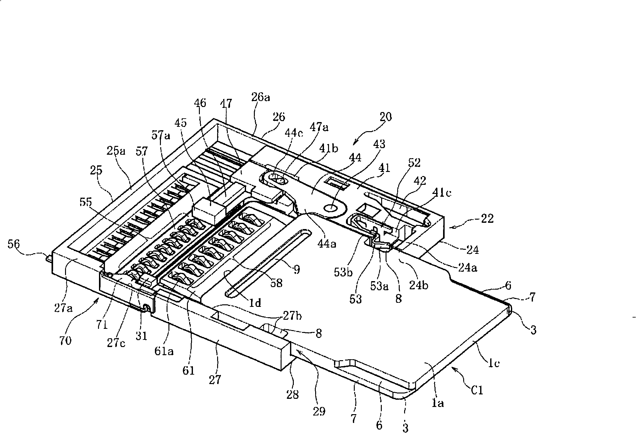
[0072] figure 1 is a perspective view showing the appearance of the card reader 20, figure 2 and image 3 It is a perspective view showing the card reader 20 with the cover removed. Figure 4 It is a front view showing the card reader 20 without a card mounted thereon seen from the front. Figure 5 It is a top view of the card reader 20 with the cover removed, Image 6 and Figure 7 It is a plan view showing a state where the first card is installed with the cover of the card reader 20 removed, Figure 8 is a plan view showing a state where the second card is installed, Figure 9 It is a plan view showing the state where the third card is installed. Figure 10 It is a partial perspective view showing the structure of the recognition detection mechanism 70 for distinguishing the first card and the second card, Figure 11 (A) and (B) are enlarged side views showing the operation of the recognition detection mechanism 70 described above.

[0073] Figure 12 In the follo...


PUM


Abstract

The present invention provides an electronic function card and a card connector mounted with the electronic function card. The card is a thin type electronic function card housed with a storage chip and the like, the shape of the cards are almost the same, and the card can easily identify the type of the internal electronic circuits. The housing (1) of a first card (C1) is in a zygomorphic rectangle shape clipping a central line (O-O). A guide identification slots (6, 6) is formed by retracting in the thickness midway from a surface (1a) at a right side section (1e) and a left side section (1f), and an intermediate dent (8, 8) is formed by retracting in the thickness midway from a surface (1a) at the rear side. The length dimensions (L1) of the guide identification slot (6, 6) are different from the categories of the internal circuit. Thus, in a guide identification slot, when the guide identification slot (6, 6) is used to guide, the type of the internal electronic circuits cam be identified by detecting the length of the guide identification slot (6, 6).

Description

technical field [0001] The present invention relates to an electronic function card in which an electronic circuit such as a memory chip is accommodated in a small and thin case made of synthetic resin, and a card connection device equipped with the electronic function card. Background technique [0002] As described in the following patent documents, a small and thin electronic function card called a "memory card" is mounted and used in a digital camera, a digital video camera, a personal computer, or the like. The electronic function card is housed in a small and thin case (sometimes referred to as a "casing") made of a synthetic resin material, and accommodates an IC chip and the like functioning as a memory chip, a memory controller, and the like. Furthermore, a plurality of external connection parts conducting with the internal electronic circuit are provided on the surface of the casing. [0003] Generally, when such an electronic function card is mounted on the card ...

Claims


Application Information

Patent Timeline
Patent Type & Authority Applications(China)
IPC IPC(8): G06K19/07G06K13/08
CPCG06K7/0047G06K13/06G06K19/077H01R13/641
Inventor 佐藤一树我妻透村山丈刚
Owner ALPS ALPINE CO LTD
Why Eureka
Try Eureka