Television wall image output system and method

A technology of image output and video wall, which is applied in the field of network video, can solve the problems of high cost of hardware decoding equipment and limited types of display equipment, and achieve the effect of reducing construction costs

Inactive Publication Date: 2009-04-08
CHINA TELECOM CORP LTD
View PDF0 Cites 22 Cited by
  • Summary
  • Abstract
  • Description
  • Claims
  • Application Information

AI Technical Summary

Problems solved by technology

[0007] The cost of hardware decoding equipment used in the existing TV wall image output system is high, and the binding relationship between the front-end and back-end equipment of each existing encoding format and the output of the decoder only use analog video signals, which limits the usable Display the type of device

Method used


Image

  • Television wall image output system and method
  • Television wall image output system and method
  • Television wall image output system and method

Examples


Embodiment Construction

[0048] The technical solutions of the present invention will be described in further detail below with reference to the accompanying drawings and embodiments.

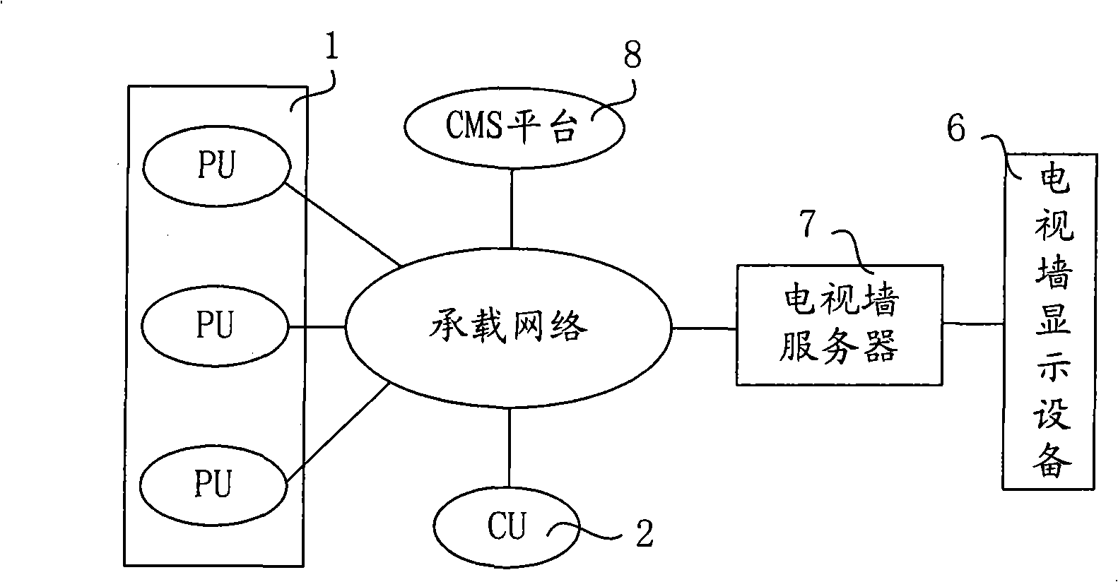
[0049] The present invention adds a video wall server to the existing video wall image output system, and uses software decoding to make simultaneous decoding and display output of multiple coded video information possible. In addition, according to the characteristics of analog and digital interfaces that large-screen display devices generally have at present, the present invention proposes to use the ability of the signal conversion module in the special video conversion output module to restore the video source of the monitoring system to analog and digital signals uniformly .

[0050] Such as image 3 As shown, it is a schematic structural diagram of an embodiment of the video wall image output system of the present invention. In the embodiment, the following components are included, namely: a front-end unit 1, a...


PUM


Abstract

The invention relates to a video wall image output system which comprises a front end unit, a central management platform, a client unit and a video wall display device which are connected by a carrying network, wherein, a video wall server is connected between the carrying network and the video wall display device and is used for calling a decoder library corresponding to the code format of a video stream to perform software decoding and reduction for the video stream, and the video wall server converts the decoded and reduced video signal into the video signal corresponding to a signal interface, and then output the signal for display. The invention further relates to a video wall image output method. The video wall image system adopts the video wall server to replace a decoding device group and a video matrix device, calls the corresponding decoding library according to various code formats to perform the software decoding, and performs signal conversion according to the signal interface supported by the video wall display device, thus reducing the construction cost; moreover, the video wall image system supports image output of the display devices of various signal interfaces, has the advantages of maintaining the output of high-definition display for a high-definition front end at a rear end and the high-definition display.

Description

technical field [0001] The present invention relates to network video technology, in particular to a video wall image output system and method Background technique [0002] In the existing implementation of video wall image output and display, the video matrix simulated by the network video surveillance system is generally used for realization, and the most important function of the video matrix is ​​to realize the switching output of the input video image, that is to say, The video matrix can switch the video image from any video input channel to any output channel, so as to realize the display control of the large screen of the TV wall. The precondition for video signal input to the video matrix and switching control on the wall is that the video input source must be an analog video (Analog Video, referred to as AV) signal, but in large-scale network video surveillance, the video source is often a variety of encoding formats (such as M-JPEG, MPEG4, H.263 and other encodin...

Claims


Application Information

Patent Timeline
Patent Type & Authority Applications(China)
IPC IPC(8): H04N7/08H04N7/24H04N7/26
Inventor 郑泽民梁笃国祁庆中孙军涛冯明谢青宇曹宁唐哲红任广杰周杰
Owner CHINA TELECOM CORP LTD
Why Eureka
Try Eureka