
Electronic ballast and general lamp seat having the same

An electronic ballast and lamp holder technology, which is applied in the field of general lamp holders for energy-saving lamps, can solve the problems of uneven flickering and dimming, high cost, complicated circuits, etc., and achieves good dimming effect, simple structure and low cost. Effect

Inactive Publication Date: 2009-04-08
GO SMART TECH SHENZHEN
View PDF0 Cites 7 Cited by
  • Summary
  • Abstract
  • Description
  • Claims
  • Application Information

AI Technical Summary

Problems solved by technology

Therefore, energy-saving lamps cannot be directly used to replace incandescent lamps in traditional dimming circuits, and users who use such dimmers cannot use energy-saving lamps on the original circuit.
[0004] With the development of electronic ballast technology, the technology of dimming energy-saving lamps using thyristor phase-modulating dimmers has also developed, but the products of the prior art have the following shortcomings: when the dimming performance reaches stability, When it is uniform and does not flicker, it has complex circuits, many components, high cost, and large volume, so it is difficult to popularize and apply; while products with simple circuits often flicker and uneven dimming when dimming, so better Dimming control circuit is the development direction of energy-saving lamp dimming technology

Method used


Image

  • Electronic ballast and general lamp seat having the same
  • Electronic ballast and general lamp seat having the same
  • Electronic ballast and general lamp seat having the same

Examples


Embodiment Construction

[0031] The following will clearly and completely describe the technical solutions in the embodiments of the present invention with reference to the accompanying drawings of the embodiments of the present invention. Obviously, the described embodiments are only some, not all, embodiments of the present invention.

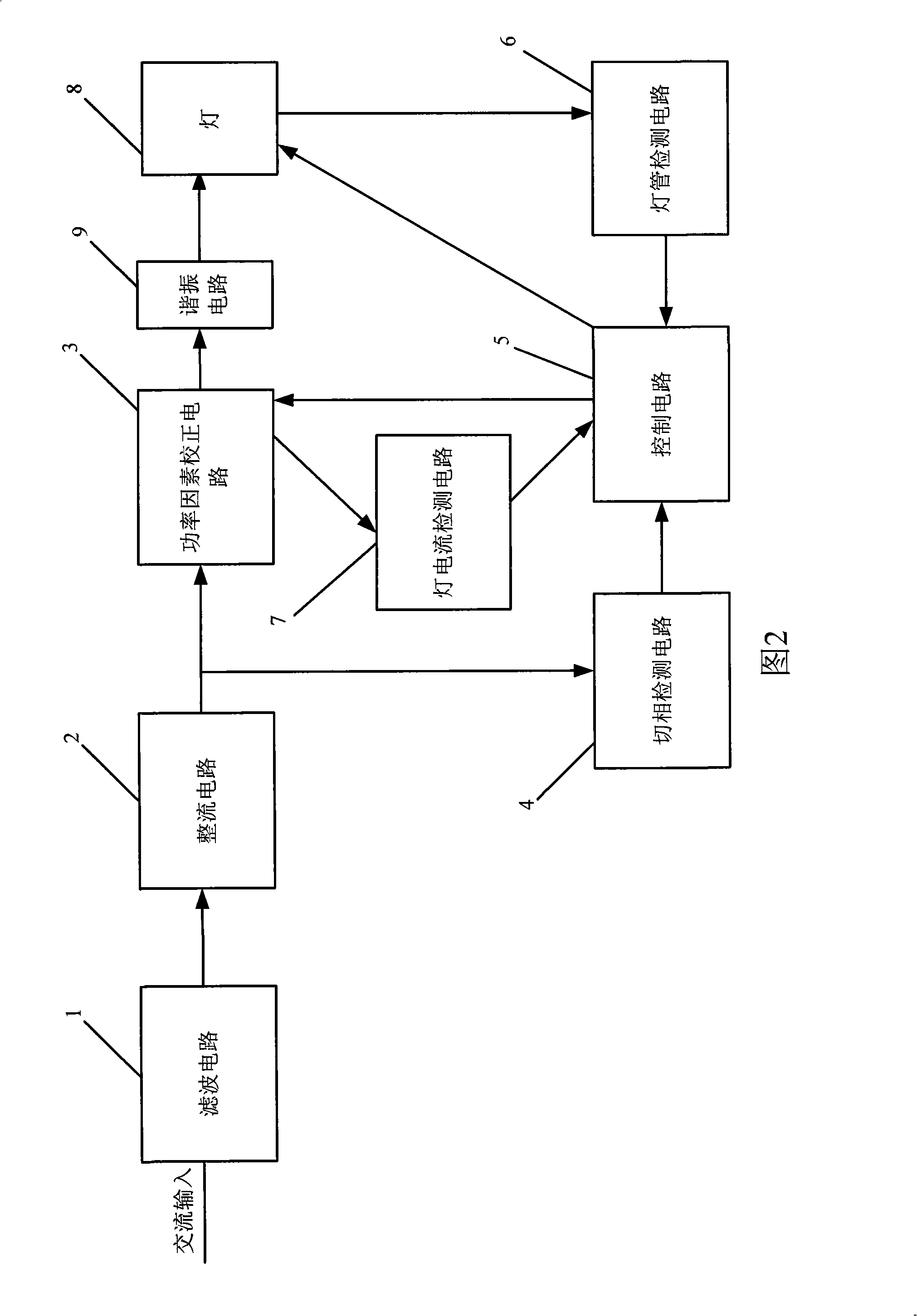
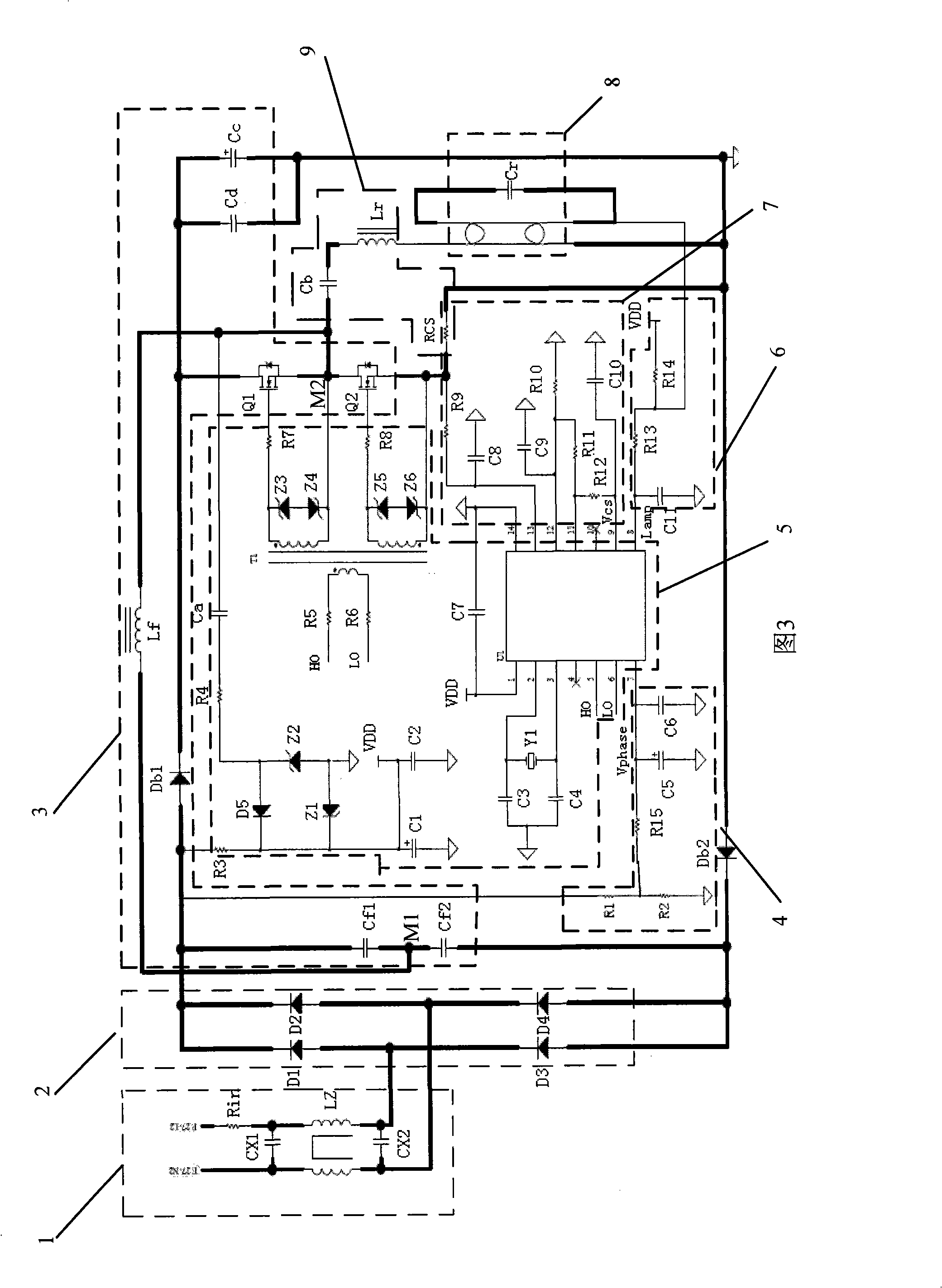
[0032] Referring to the accompanying drawings, Fig. 2 is a functional block diagram of an embodiment of the dimmable energy-saving lamp electronic ballast of the present invention. The electronic ballast in this embodiment includes a filter circuit 1 , a rectifier circuit 2 , a power factor correction circuit 3 , a phase cut detection circuit 4 , a control circuit 5 , a lamp detection circuit 6 , a lamp current detection circuit 7 and a resonance circuit 9 .

[0033] 3, the filter circuit 1 is an EMC filter circuit, including filter elements CX1, CX2, Rin and a Π-type filter, and its input end is connected to the city AC power supply through a dimmer to filter out hig...


PUM


Abstract

The invention discloses an electronic ballast which comprises a filter circuit, a rectification circuit, a phase shedding detection circuit, a power factor correction circuit, a resonance circuit and a control circuit. The filter circuit and the rectification circuit are connected with an alternating power supply. One end of the phase shedding detection circuit is connected with an output end of a rectification circuit, and the other end thereof is connected with the control circuit. The power factor correction circuit is connected with the output end of the rectification circuit and comprises a half-bridge which consists of two switch transistors connected in series. One end of the resonance circuit is connected with the output end of the half-bridge, and the other end thereof is connected with a lighting tube. The control circuit is connected with control ends of the switch transistors, and the control circuit controls the switch transistors to be switched on and off and the output frequency of the half-bridge by a detection signal of the phase shedding detection circuit. The electronic ballast has simple circuit, low cost and good dimming effect. The invention also discloses a universal lamp holder of an energy saving lamp with the electronic ballast and a dimming method used by the electronic ballast.

Description

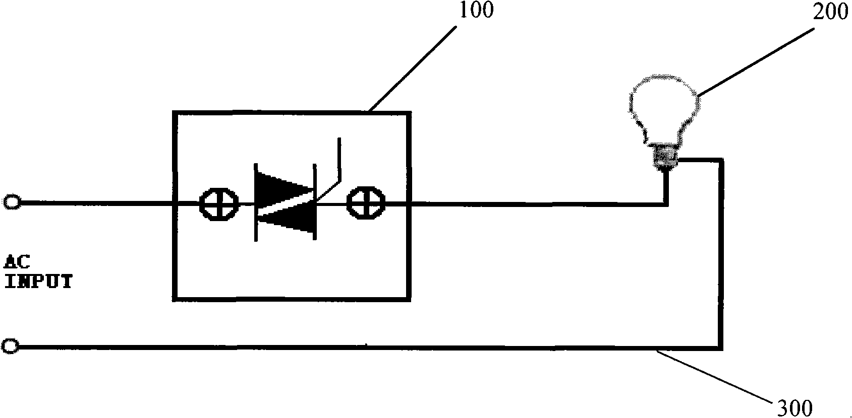
technical field [0001] The invention relates to a ballast, in particular to a dimmable electronic ballast for an energy-saving lamp and a universal lamp holder for an energy-saving lamp with the electronic ballast. Background technique [0002] In people's daily life, light bulbs are widely used. Such as figure 1 As shown, the traditional incandescent lighting circuit includes: an AC input, a phase-cut dimmer 100 for adjusting the brightness of the incandescent lamp, an incandescent lamp 200 and a circuit 300 . Because the use efficiency of incandescent lamps is relatively low and the service life is short, with the improvement of living requirements and the enhancement of environmental protection awareness, people have turned their attention to durable, flexible and environmentally friendly energy-saving lamps. [0003] However, the existing phase-cut dimmer 100 is usually controlled by a triac, and this type of dimmer cannot be used to control energy-saving lamps. This ...

Claims


Application Information

Patent Timeline
IPC IPC(8): H05B41/295
Inventor 陶伟洪
Owner GO SMART TECH SHENZHEN
Learn More