Permanent magnetic levitation train with magnetic levitation energy storage flywheel as power

A technology for magnetic levitation trains and energy storage flywheels, applied in electric vehicles, electric traction, vehicle components, etc., can solve problems such as increased train failure rate, many structural coils, complex manufacturing, etc., to achieve easy manufacturing and maintenance, and increase suspension The effect of small force and vibration

Inactive Publication Date: 2009-04-15
孙昊天
View PDF0 Cites 7 Cited by
  • Summary
  • Abstract
  • Description
  • Claims
  • Application Information

AI Technical Summary

Problems solved by technology

At present, the maglev train mainly adopts the following three technologies: one is to install the levitation electromagnetic coil and the running transmission electromagnetic coil on the entire track, this structure has many coils, consumes a lot of energy, is complicated to manufacture, and is inconvenient to maintain; the other is to install the levitation The electromagnetic coil and the running transmission electromagnetic coil are installed on the train, and the electric power is led to the train through the current receiver (sliding contact). This structure does not make the train completely suspended, and the sliding contact of the current receiver increases the running speed of the train. The failure rate is not suitable for high-speed trains; another is to install the running transmission electromagnetic coil on the rail. This structure also consumes a lot of energy, is complicated to manufacture, and is inconvenient to maintain.

Method used


Image

  • Permanent magnetic levitation train with magnetic levitation energy storage flywheel as power
  • Permanent magnetic levitation train with magnetic levitation energy storage flywheel as power
  • Permanent magnetic levitation train with magnetic levitation energy storage flywheel as power

Examples


Embodiment Construction

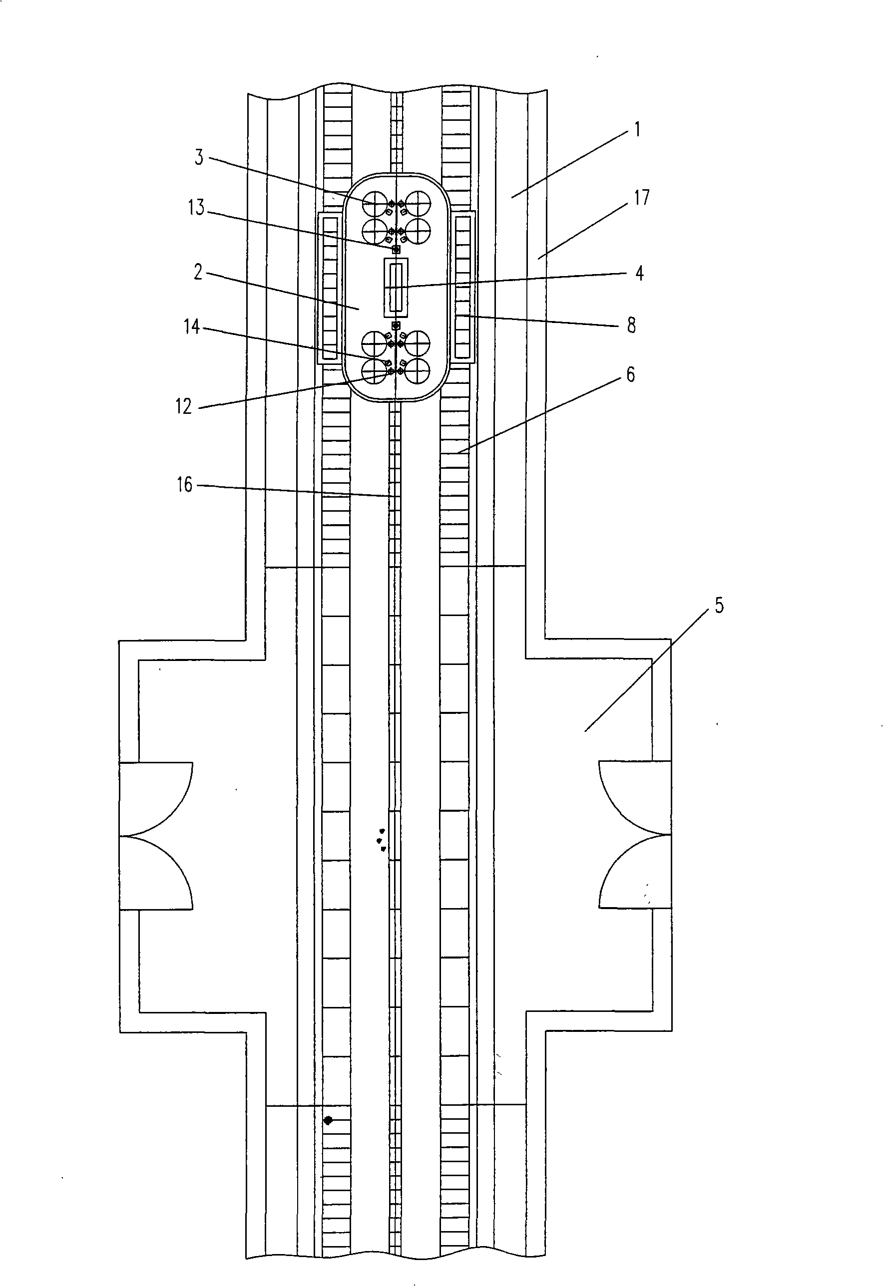
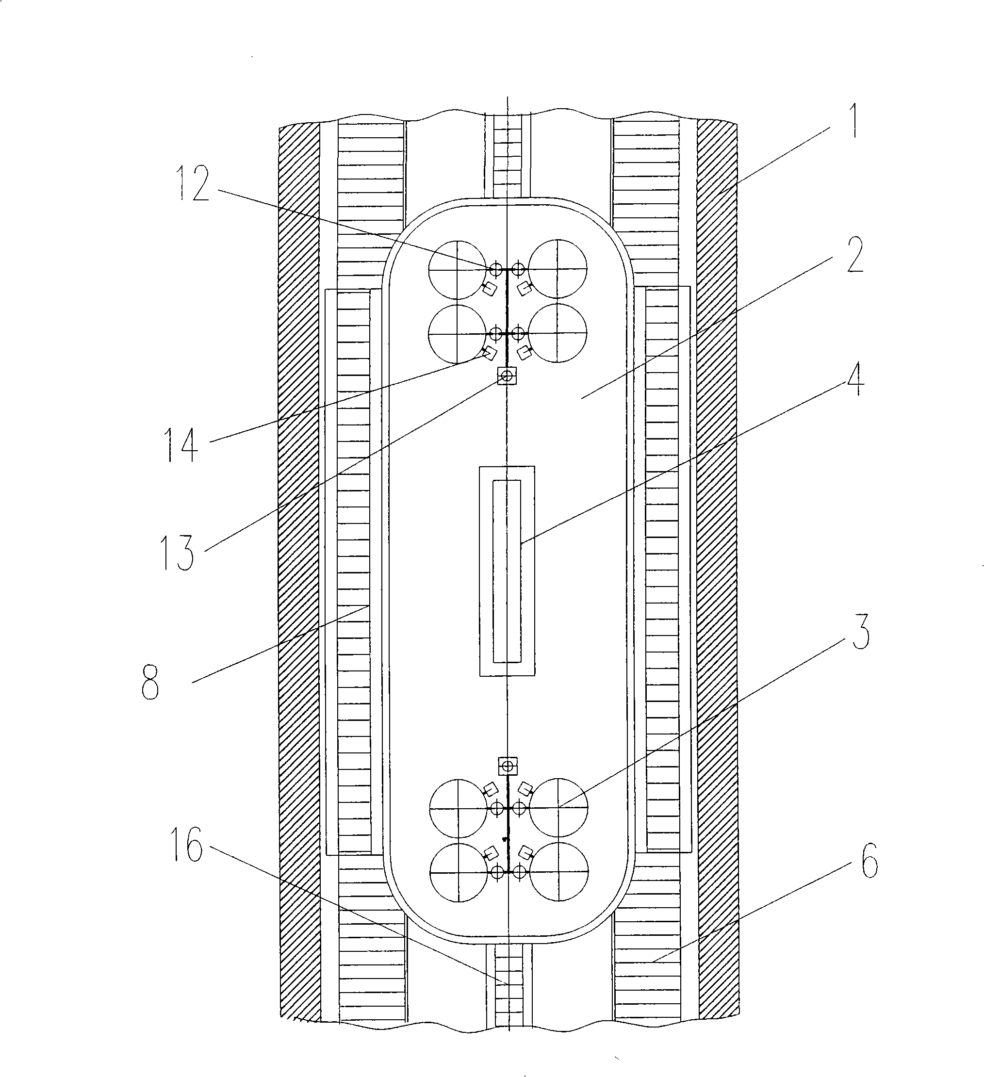
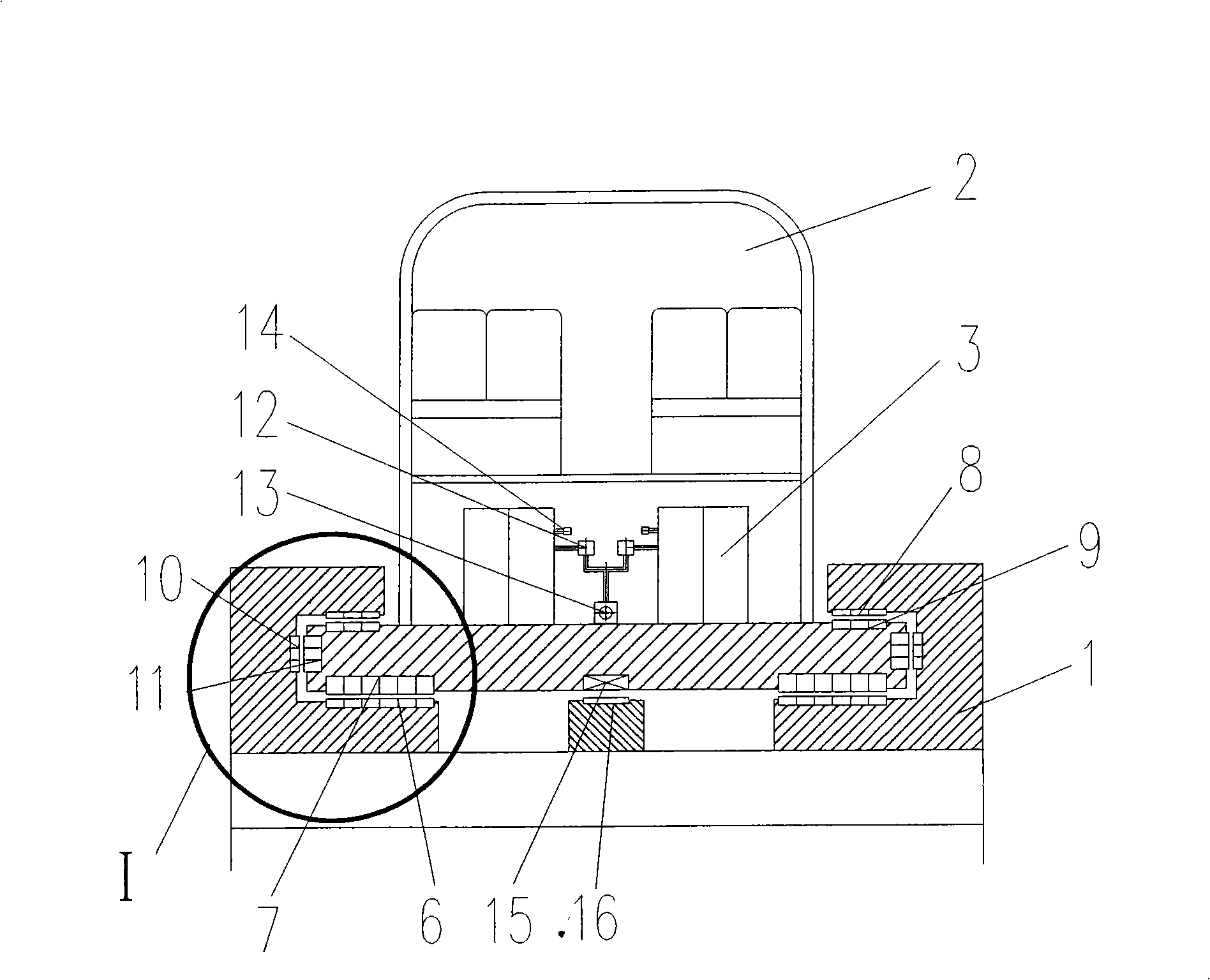
[0010] Depend on figure 1 , figure 2 , image 3 , Figure 4 As can be seen, the present invention is mainly made up of rail 1, car body 2, energy storage flywheel 3, control system 4, parking station 5 etc., main suspension magnet 6 and 7 are respectively housed on rail 1 and car body 2, and main suspension magnet 6 and 7 are composed of magnets with opposite polarities, that is, the N pole is opposite to the N pole, and the S pole is opposite to the S pole, so that the train is suspended at a certain height. The parts are all made of NdFeB rare earth permanent magnets, and the main suspension magnet 7 is NdFeB rare earth permanent magnets; the rail 1 and the car body 2 are also equipped with auxiliary suspension magnets 8 and 9 respectively to keep the train running stably , to reduce up and down fluctuations, the auxiliary levitation magnets 8 and 9 are installed in the opposite direction of the main levitation magnets 6 and 7, and are composed of magnets with opposite p...


PUM


Abstract

The invention discloses a permanent-magnet suspension train using a magnetic suspension energy storage flywheel as power, which comprises a rail, a train body, an energy storage flywheel, a control system and a stop. The rail and the train body are respectively provided with a main suspension magnet, an auxiliary suspension magnet and a guiding suspension magnet made from rare-earth permanent magnet materials of neodymium iron boron; the train body is also provided with the energy storage flywheel which can convert electrical energy into mechanical energy to store and convert the mechanical energy into the electrical energy, so as to provide the electrical energy required when the train runs and a vacuum machine set works, and the like; the energy storage flywheel is supported by a magnetic suspension bearing, and a shell of the energy storage flywheel is connected with the vacuum machine set through a vacuum valve; and the vehicle body and the rail are respectively provided with a coil of a linear magnetoelectric machine and a magnet stator of an electric motor. A transmission system has a simple structure, is easy to manufacture and maintain, and saves energy, so that the train runs more stably, has low vibration and low noise, and can not affect normal life of people when passing through a residential area.

Description

technical field [0001] The invention relates to a magnetic suspension train, in particular to a permanent magnetic suspension train powered by a magnetic suspension energy storage flywheel. Background technique [0002] With the progress of society and the continuous development of science and technology, the transportation industry will usher in an unprecedented development opportunity. With its advantages of no contact with the guide rail, small vibration, low noise, fast speed, and no pollution, the maglev train will definitely play an important role in the future transportation industry and become a major means of transportation, just like the emergence of automobiles. Just like human life, after the maglev train technology is widely used, it will definitely change the life and living style of human beings again, which has epoch-making significance. At present, the maglev train mainly adopts the following three technologies: one is to install the levitation electromagne...

Claims


Application Information

Patent Timeline
Patent Type & Authority Applications(China)
IPC IPC(8): B60L13/10
Inventor 孙昊天
Owner 孙昊天
Why Eureka
Try Eureka