Method and structure for fibrous web debatching device

A fiber web, web technology, applied in the direction of winding strip, transportation and packaging, thin material handling, etc., can solve the problems of small average running speed, loss of production volume, etc.

Active Publication Date: 2009-04-15
METSO PAPER INC
View PDF2 Cites 4 Cited by
  • Summary
  • Abstract
  • Description
  • Claims
  • Application Information

AI Technical Summary

Problems solved by technology

But this approach may result in a small average running speed, which again leads to a loss of throughput

Method used


Image

  • Method and structure for fibrous web debatching device
  • Method and structure for fibrous web debatching device
  • Method and structure for fibrous web debatching device

Examples


Embodiment Construction

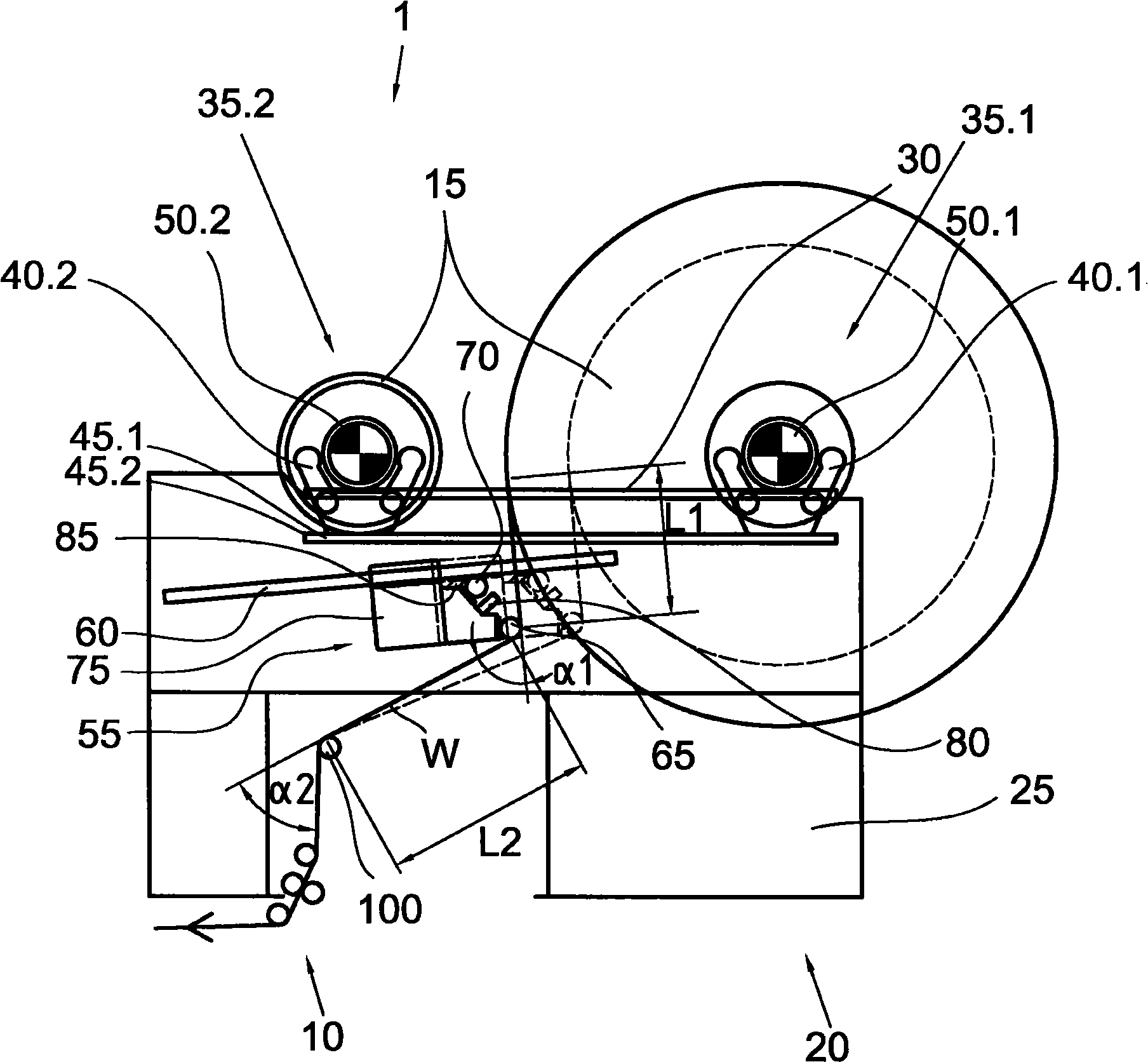
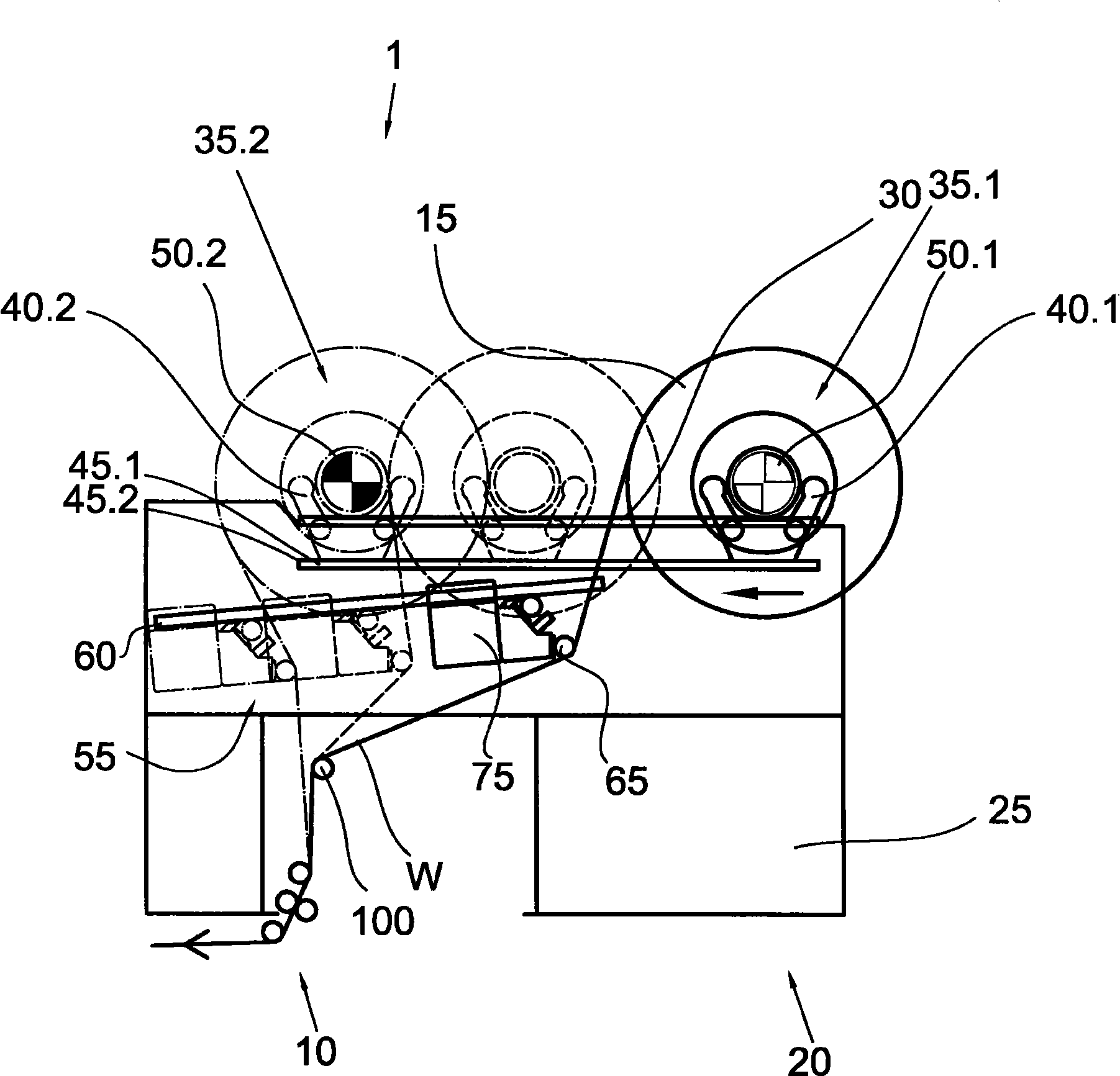
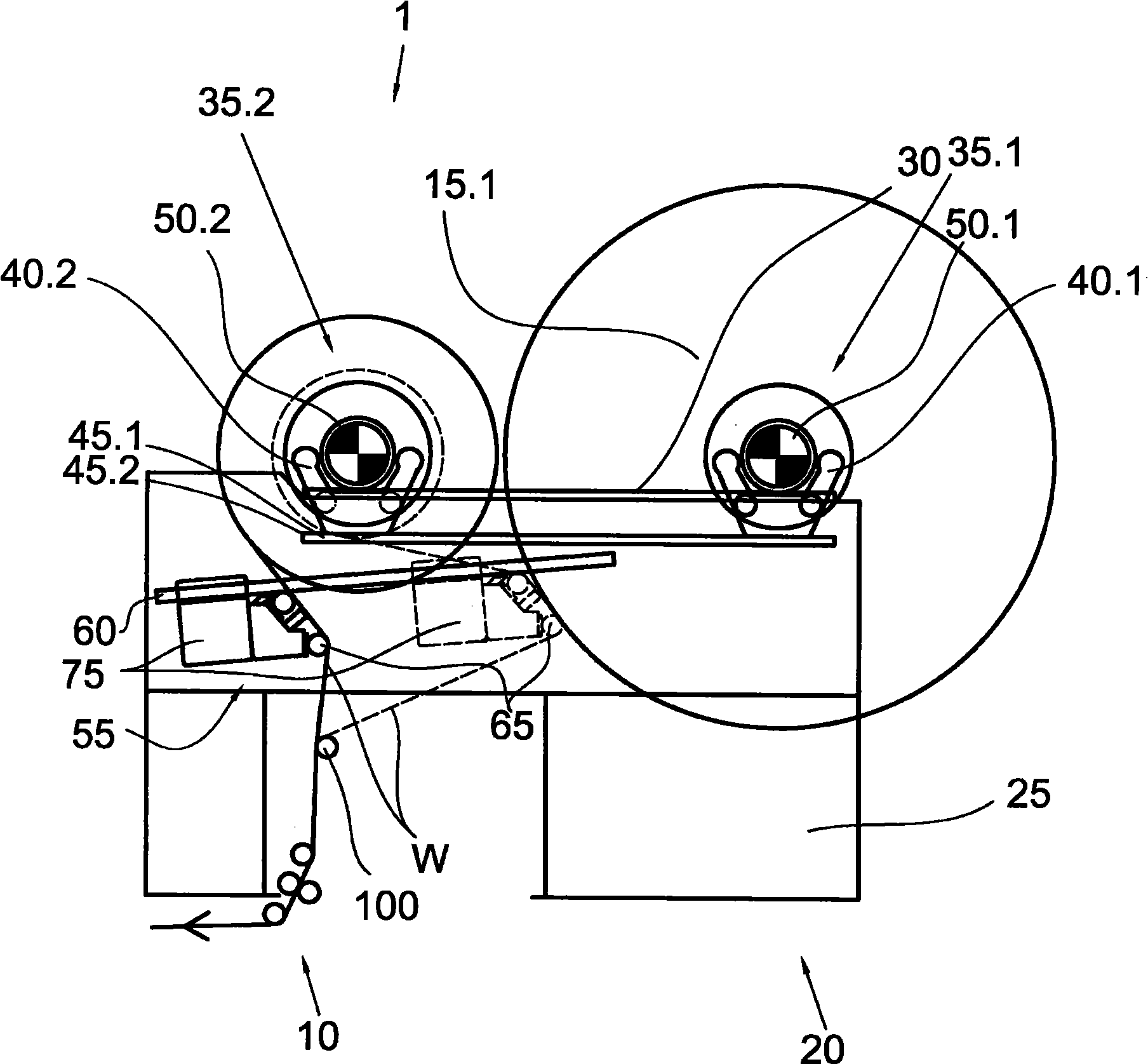
[0024] According to an embodiment of the present invention, in figure 1 A side view of the cutting section 10 of the longitudinal web slitting machine 1 and the subsequently arranged unwinding device 20 for the machine roll 15 is schematically shown in FIG. Part of the web unwinder that functionally belongs to the longitudinal slitter is not shown for the sake of clarity of the drawing. The unwinding device comprises a frame 25 supported on a base (not shown). A plurality of rails 30 are arranged in parallel and in the same direction on the machine frame 25 , so that the machine reels 15 are supported in the same manner via bearings at both ends of the reel shaft (only one is shown). The unwinding device comprises a first unwinding station 35.1 and a second unwinding station 35.2 at which, in the illustrated embodiment, fixed drives 50.1 and 50.2 are provided. The two drives are provided with motors and connection means (not shown) by means of which the motors can be connect...


PUM


Abstract

The invention relates to a method using a longitudinal cutter for longitudinally splitting a fiber web, wherein, by executing re-rolling of a predetermined length, the web (W) which is cut into part web by the longitudinal cutter is rolled up to a part of web roll with a predetermined diameter. The method involves rolling a machine roll (15) up to a predetermined diameter in a primary rolling station (35.1). The machine roll is shifted to a secondary rolling station (35.2), and a machine roll change is implemented during connection of a fiber web (W) arriving from the new machine roll with a web arriving from an old machine roll that is connected with a splitting connection. The machine roll is shifted from the primary rolling station to the secondary rolling station during the roll change of a longitudinal cutter. An independent claim is also included for an arrangement for slitting a longitudinal cutter of a fiber web.

Description

technical field [0001] The subject matter of the invention is the unwinding of the fibrous web and the unwinding device for the fibrous web. The subject matter of the invention is in particular the unwinding performed during longitudinal slitting of the fibrous web. [0002] To this end, the invention relates to a method for longitudinally slitting a fibrous web by means of a longitudinal slitter (1) according to the preamble of claim 1, wherein the longitudinally slit A web slit into partial webs is wound into partial web rolls having a certain diameter. In the first unwinding position ( ) after the unwinding machine roll (Maschinenrolle) is unrolled to a certain diameter, it moves to the second unwinding position, where the machine roll with the remaining web is unrolled and the machine roll is replaced, which is Said to convert the machine roll to be unwound at the second unwinding position (auslaufende) into a new machine roll unwound at the first unwinding position, w...

Claims


Application Information

Patent Timeline
Patent Type & Authority Applications(China)
IPC IPC(8): B65H35/02B65H19/18B65H19/20B65H16/00B65H18/08B65H23/00
CPCB65H2301/4148B65H2301/41734B65H19/12B65H2301/41361B65H19/126B65H19/1815B65H23/1888
Inventor 肯尼思·阿克尔隆德马尔库·耶尔文斯沃
Owner METSO PAPER INC
Why Eureka
Try Eureka