Method and device for operating open-end spinning machine

A technology of rotor spinning and free end, which is applied in the direction of free end spinning machine, spinning machine, continuous winding spinning machine, etc., can solve the problems such as putting forward excessive requirements, reduce the burden, reduce the rate of strain, reduce the burden effect

Active Publication Date: 2009-04-15
SAURER GERMANY GMBH & CO KG
View PDF4 Cites 15 Cited by
  • Summary
  • Abstract
  • Description
  • Claims
  • Application Information

AI Technical Summary

Problems solved by technology

However, in particular under unfavorable conditions, a large amount of auxiliary work is performed in connection with the operation of such a rotor spinning ma

Method used


Image

  • Method and device for operating open-end spinning machine
  • Method and device for operating open-end spinning machine

Examples


Embodiment Construction

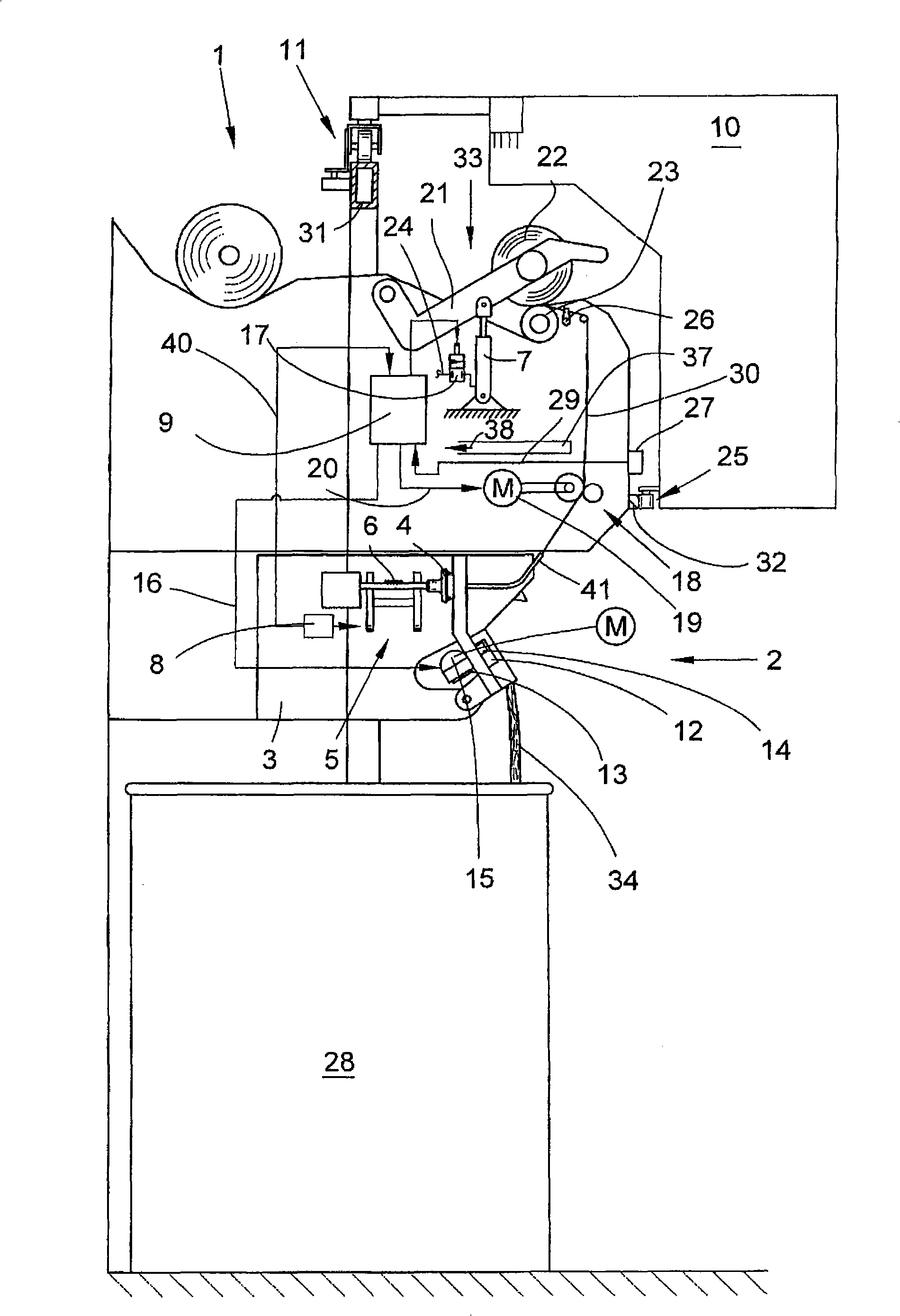
[0023] figure 1 One half of an open-end rotor spinning machine 1 according to the invention is shown. Such a spinning machine has a plurality of stations 2 which are each equipped with a spinning device 3 and a winding device 33 . The fiber ribbon 34 supplied in the spinning drum 28 is spun into yarns 30 in the spinning device 3 , and the yarns 30 are wound into a cross-wound bobbin 22 on a winding device 33 .

[0024] For this purpose, the winding device 33 has, as it is known per se, a creel 21 for rotatably holding a tube of a cross-wound bobbin 22; a bobbin drive roller 23; a yarn traversing mechanism 26 and A mechanism 7 for lifting the cross-wound bobbin 22 from the bobbin drive roller 23 . The mechanism 7 is designed, for example, as a thrust piston drive, which is connected to an excess pressure source (not shown) via a pneumatic line 24 into which the solenoid valve 17 is connected.

[0025] In this embodiment, the bobbin drive roller 23 is driven in the form of a ...


PUM


Abstract

The invention relates to a method and device for operating an open end rotor spinning machine. The open end rotor spinning machine involves a set of homogeneous workplaces, each provided with a spinning device for producing spinning and a winding device for manufacturing cross winding bobbing. These workplaces are configured that a thread end which is returned from the cross winding bobbing after spinning interruption, prepared for splicing process and placed in the splicing position, is automatically started to spin by the device. Time-critical steps of a spinning start process such as defined return of the thread end in a spinning rotor, exact starting of a thread supply and exact beginning of distraction of a thread from an open end spinning device, are realized by workplace-own devices. Assisting operations before starting the spinning start process are executed by a service assembly automatically operating the workplaces.

Description

technical field [0001] The invention relates to a method and a device for operating an open-end rotor spinning machine according to the preamble of claim 1 . Background technique [0002] Open-end rotor spinning machines are used in the textile industry in many different embodiments and are described in detail in numerous patent applications. [0003] An open-end rotor spinning machine is described, for example, in DE 198 36 065 A1, which, as usual, has a plurality of stations of the same type arranged sequentially in rows, at which stations, preferably the corresponding fibers supplied by the spinning bobbin The tapes are spun into yarns and then wound into cross-wound bobbins. For this purpose, each station has a spinning device and a winding device, the working mechanism of the spinning device and the working mechanism of the winding device are both driven by a drive arranged in the longitudinal direction of the machine. That is to say, the tangential belts for driving ...

Claims


Application Information

Patent Timeline
IPC IPC(8): D01H4/50D01H4/00B65H67/08
CPCD01H15/00B65H2701/31B65H67/081D01H4/50B65H54/26
Inventor 拉尔夫·西韦特
Owner SAURER GERMANY GMBH & CO KG
Why Eureka
Try Eureka