Wind turbine geothermal heating and cooling system

A technology for wind turbines and heat transfer systems, applied in the field of components or units, to solve problems such as geothermal cooling of heat exchangers

Inactive Publication Date: 2009-04-15
GENERAL ELECTRIC CO
View PDF0 Cites 3 Cited by
  • Summary
  • Abstract
  • Description
  • Claims
  • Application Information

AI Technical Summary

Problems solved by technology

The heat exchanger is cooled by geothermal

Method used


Image

  • Wind turbine geothermal heating and cooling system
  • Wind turbine geothermal heating and cooling system

Examples


Embodiment Construction

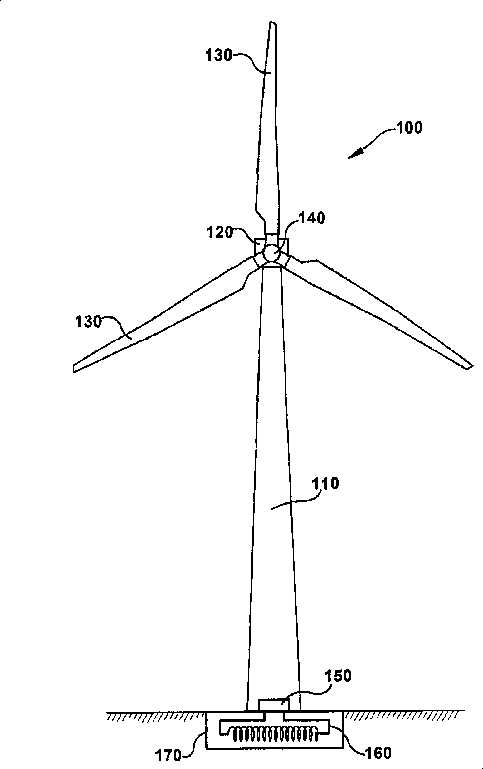
[0015] A horizontal axis wind turbine (HAWT) 100 (hereinafter "wind turbine") such as figure 1 shown. However, the present invention may be applied with any wind turbine, including, but not limited to, vertical axis wind turbines. Wind turbine 100 may include a tubular tower 110, which is often fabricated from steel. Tower 110 may be erected by stacking multiple tower sections on top of each other. Tower 110 supports the weight of nacelle 120 , blades 130 and hub 140 . The tower may also be of the lattice (or truss) type, and the tubular tower may alternatively be formed of concrete or other suitable material. The nacelle 120 typically houses the drive train (eg, gearboxes, shafts, couplings, generators, etc.), as well as the main frame (also known as the chassis) and the yaw drives. Other items such as control electronics may also be housed within the nacelle 120 or in the tower 110 . Typically, nacelle 120 has an outer layer constructed of a lightweight material such as...


PUM


Abstract

The present invention relates to a wind turbine geothermal heating and cooling system. Specifically a wind turbine having a tower and a nacelle, includes at least one unit to be heated or cooled. The unit can be housed within the tower or nacelle. A geothermal heat exchanger can be located inside the tower or nacelle. A geothermal cooling circuit provides flow communication between the unit to be heated or cooled and the heat exchanger, and contains a thermal transfer medium flowing between the unit and the heat exchanger for facilitating heating or cooling of the unit.

Description

technical field [0001] The present invention relates generally to a wind turbine having at least one unit or component to be heated and / or cooled, and more particularly to at least one component or unit of a wind turbine heated and / or cooled using a geothermal system. Background technique [0002] Recently, wind turbines have gained increased attention as an environmentally safe and relatively inexpensive alternative energy source. Wind turbines do not emit greenhouse gases (GHGs) and thus do not contribute to global warming. Wind turbines also allow a country to become more energy independent through domestic electricity production. With the growing interest in wind power generation, considerable efforts have been made to develop reliable and efficient wind turbines. [0003] Wind is generally considered a form of solar energy caused by the sun's uneven heating of the atmosphere, irregularities in the Earth's surface, and the Earth's rotation. Wind flow patterns are modi...

Claims


Application Information

Patent Timeline
Patent Type & Authority Applications(China)
IPC IPC(8): F03D1/00F03D11/00
CPCF03D9/02Y02E10/722F03D11/00Y02E10/726F03D9/00F03D9/10F03D80/00Y02E10/72Y02E10/728Y02E70/30Y02P80/10F03D13/22F03D80/60
Inventor E·D·埃格尔斯顿
Owner GENERAL ELECTRIC CO
Why Eureka
Try Eureka