
Method for preparing sensitive coil of reflection type optical fiber current sensor

A fiber optic current and sensitive coil technology, applied in the direction of voltage/current isolation, measuring current/voltage, instruments, etc., can solve the problems that the optical fiber cannot be completely fixed, the stress of the sensitive optical fiber is large, and the coefficient of linear expansion is large, so as to avoid errors and resist Good shock vibration performance and stress uniform effect

Active Publication Date: 2009-04-15
BEIJING AEROSPACE TIMES OPTICAL ELECTRONICS TECH
View PDF0 Cites 20 Cited by
  • Summary
  • Abstract
  • Description
  • Claims
  • Application Information

AI Technical Summary

Problems solved by technology

The sensitive coil described in this method needs to be annealed for optical fiber stress relief, and the optical fiber cannot be completely fixed in the capillary, so the stress it receives will change with changes in external conditions
[0005] In addition, the stress generated by the sensitive optical fiber coil with temperature changes can be compensated by temperature control, while the sensitive coil skeleton is affected by temperature changes, and the stress caused by structural deformation depends on the material of the skeleton structure. The greater the material expansion rate, The more severe the deformation of the skeleton structure, the greater the stress it may cause on the sensitive fiber, resulting in nonlinearities that are difficult to compensate
Metal materials have good processability and low cost, but the coefficient of linear expansion is large, so the coil bobbin made of it is easily affected by stress

Method used


Image

  • Method for preparing sensitive coil of reflection type optical fiber current sensor
  • Method for preparing sensitive coil of reflection type optical fiber current sensor
  • Method for preparing sensitive coil of reflection type optical fiber current sensor

Examples


Embodiment Construction

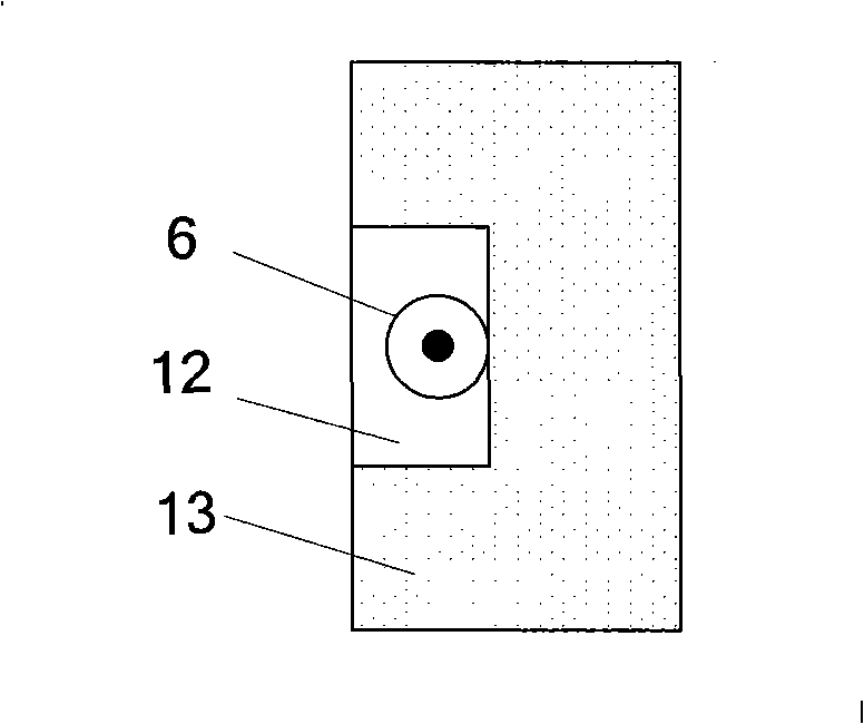
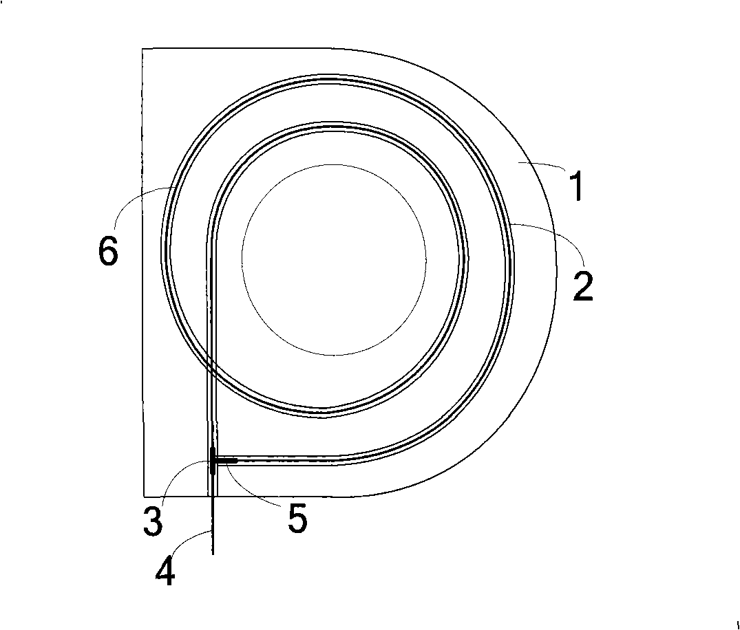
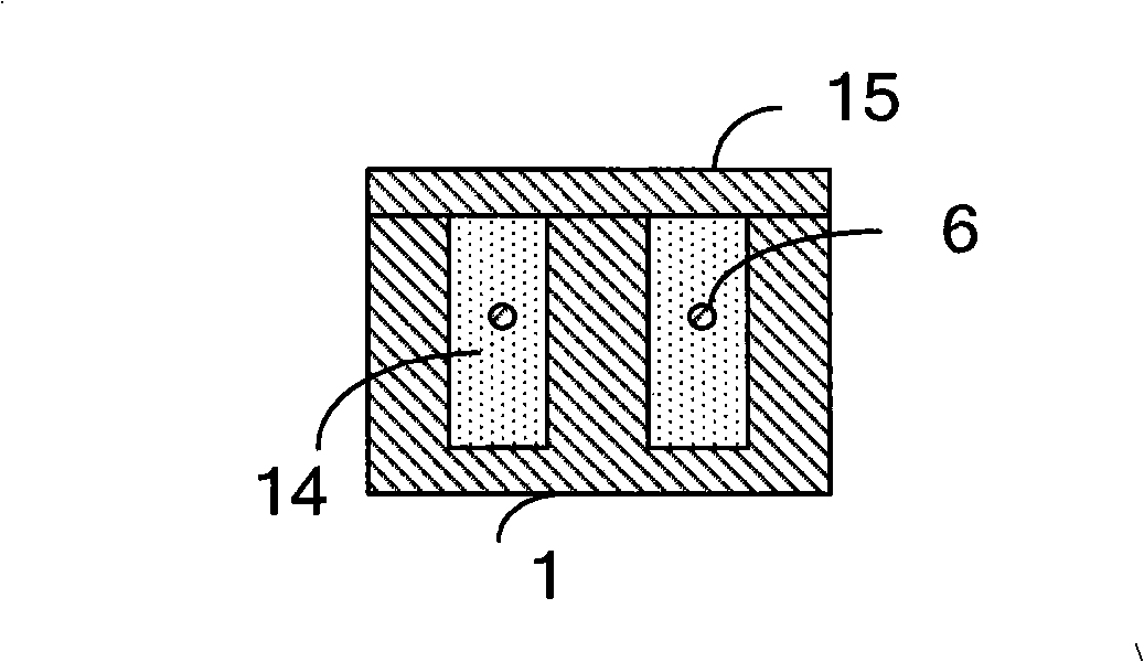
[0025] Such as figure 2 As shown, the present invention uses aluminum alloy with relatively low density and low cost to process the annular sensitive coil bobbin 1, and the surface of the coil bobbin 1 is anodized to avoid the influence of metal oxidation on the coil. A groove 2 shaped as an Archimedes spiral is processed on the coil bobbin, its radial cross-section is trapezoidal or rectangular, the groove depth is 1-5mm, the groove width is 1-5mm, the groove spacing is 2-10mm, and the groove depth is generally selected 2mm, groove width 2mm, groove spacing 4mm. The circumferential shape of the groove 2 is an Archimedes spiral, and there are tangent extensions at the beginning and the end of the spiral, and they intersect vertically.

[0026] During processing, use a syringe with a smaller outlet to apply the optical fiber paste in the groove 2, with a height of 0.8-1.2mm, and use a tool that can only extend into the groove 2 for 0.8-1.2mm to scrape the optical fiber paste ...


PUM

PropertyMeasurementUnit
Groove depthaaaaaaaaaa
Groove widthaaaaaaaaaa

Abstract

The invention relates a method for making a sensor coil of a reflective optical fiber current sensor. A groove which takes the shape of the spiral of Archimedes is processed on a ring-shaped metallic framework, and sensitive fiber is wound in the groove; after filled with fiber paste and fixed, the groove is sealed; finally, the stress on the sensitive fiber is released by temperature ictus and vibration, thus causing the state of the sensitive fiber to be stable. The method of the invention can ensure that the sensitive fiber coil has good stability even under certain perturbation and can guarantee the ideal measuring precision; meanwhile, in the method of the invention, the metallic framework is adopted, so as to reduce the making difficulty and cost and realize the consistency of winding easily with respect to the technique.

Description

technical field [0001] The invention relates to a reflective optical fiber current sensor, in particular to a sensitive optical fiber coil for the reflective optical fiber current sensor. Background technique [0002] The fiber optic current sensor is a photoelectric sensor based on the Faraday effect and sensitive to the current passing in the conductor. Because of its advantages of high voltage insulation, high safety and reliability, and low maintenance costs, it has a good market prospect, especially The reflective fiber optic current sensor has better performance due to its better reciprocity. [0003] In the reflective fiber optic current sensor, the left-handed and right-handed circularly polarized light transmitted in the sensitive coil will induce different phase changes after the magnetic field generated by the current to be measured, and then by demodulating the phase difference between the left-handed and right-handed circularly polarized light waves Get the mag...

Claims


Application Information

Patent Timeline
IPC IPC(8): G01R15/24G01R19/00
Inventor 王学锋王巍张志鑫单联洁
Owner BEIJING AEROSPACE TIMES OPTICAL ELECTRONICS TECH
Learn More