
Method and structure of projector bulb heat radiation

A technology of a heat dissipation structure and a heat dissipation method, applied in the field of projectors, can solve the problems of poor heat dissipation effect of lamp cups and inability to dissipate heat, and achieve the effect of avoiding uneven heat dissipation and accelerating heat dissipation and enhancing the heat dissipation effect.

Active Publication Date: 2009-04-15
HISENSE VISUAL TECH CO LTD
View PDF1 Cites 3 Cited by
  • Summary
  • Abstract
  • Description
  • Claims
  • Application Information

AI Technical Summary

Problems solved by technology

This heat dissipation structure can dissipate heat well from the lamp body, but the heat dissipation effect on the interior of the lamp cup is not good, especially the key points of the temperature rise of the bulb cannot be dissipated in a targeted manner.

Method used


Image

  • Method and structure of projector bulb heat radiation
  • Method and structure of projector bulb heat radiation
  • Method and structure of projector bulb heat radiation

Examples


Embodiment Construction

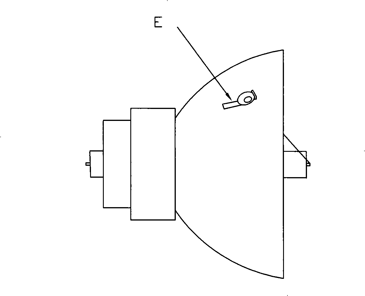
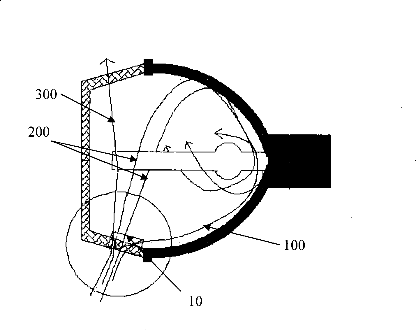
[0034] In order to enhance the heat dissipation effect of the projector bulb, the embodiment of the present invention provides a method and structure for heat dissipation of the projector bulb, which can dissipate heat to different parts inside the bulb, especially the key temperature rise parts, and improve the heat dissipation. Effect. The embodiments of the present invention will be described in detail below in conjunction with the accompanying drawings.

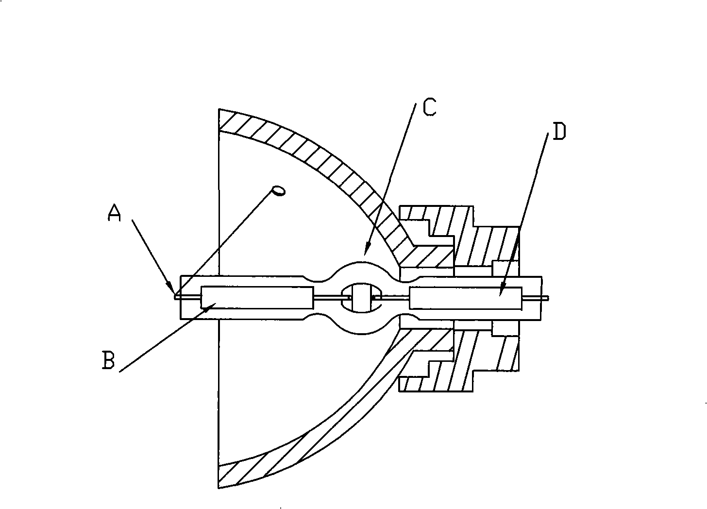
[0035] The bulb of the embodiment of the present invention adopts a high-pressure mercury lamp. figure 1 Shown is the internal structure of the bulb in this embodiment. In order to effectively and evenly dissipate heat from the light bulb in this embodiment, the key temperature-rising parts inside the light bulb are analyzed first. It can be seen from the figure that there are four key temperature rise parts A, B, C, and D inside the bulb, and the temperature rise requirements of each part are different.

[0036] Next,...


PUM


Abstract

The invention discloses a heat dissipation method for a bulb of a projection machine and a structure thereof and relates to the projection machine in order to solve the problem that the bulb of the projection machine can dissipate heat evenly. The heat dissipation method for the bulb of the projection machine comprises the steps as follows: air stream entering a lamp cup is shunted; after entering the lamp cup, the shunted air stream is discharged after the air stream respectively flows through the different positions of the lamp cup. In the dissipation structure of the bulb of the projection machine, a stream guidance component is arranged at the inlet opening of the lamp cup. The invention is suitable for a dissipation system of the bulb of the projection machine, and is also suitable for other components or systems that dissipate the heat by wind cooling.

Description

technical field [0001] The invention relates to a projector, in particular to a heat dissipation method and structure of a projector bulb. Background technique [0002] At present, with the increasing function and complexity of electronic products, the power consumption continues to increase, and the loss of power is usually converted into a certain amount of heat energy. The miniaturization requirements of electronic products also cause the heat flux density of the product (that is, the heat transferred through the unit heat transfer area per unit time) to rise sharply, resulting in a rapid increase in the temperature rise of electronic products. If the heat dissipation cannot be effectively performed, the reliability of the product will be seriously affected and service life. [0003] The temperature rise problem caused by the sharp rise of heat flux is particularly prominent in projector products. According to the imaging principle of the projector, the strong light emi...

Claims


Application Information

Patent Timeline
IPC IPC(8): G03B21/16H05K7/20
Inventor 李春圃邵小军
Owner HISENSE VISUAL TECH CO LTD
Learn More