Touch panel

A touch panel and substrate technology, applied in the direction of instruments, electrical digital data processing, data processing input/output process, etc., can solve the problems of unstable electrical connection and separation, difficulty in seeing the display of touch panel display components, etc., and achieve recognition Excellent, reliable operation, and the effect of suppressing condensation

Inactive Publication Date: 2009-04-15
PANASONIC CORP
View PDF1 Cites 7 Cited by
  • Summary
  • Abstract
  • Description
  • Claims
  • Application Information

AI Technical Summary

Problems solved by technology

Due to this condensation, it is difficult to see the display of the display elements on the back of the touch panel 100.
Furthermore, the electrical connection between the upper conductive layer 103 and the lower conductive layer 104 becomes unstable.

Method used


Image

  • Touch panel
  • Touch panel
  • Touch panel

Examples


Embodiment approach 1

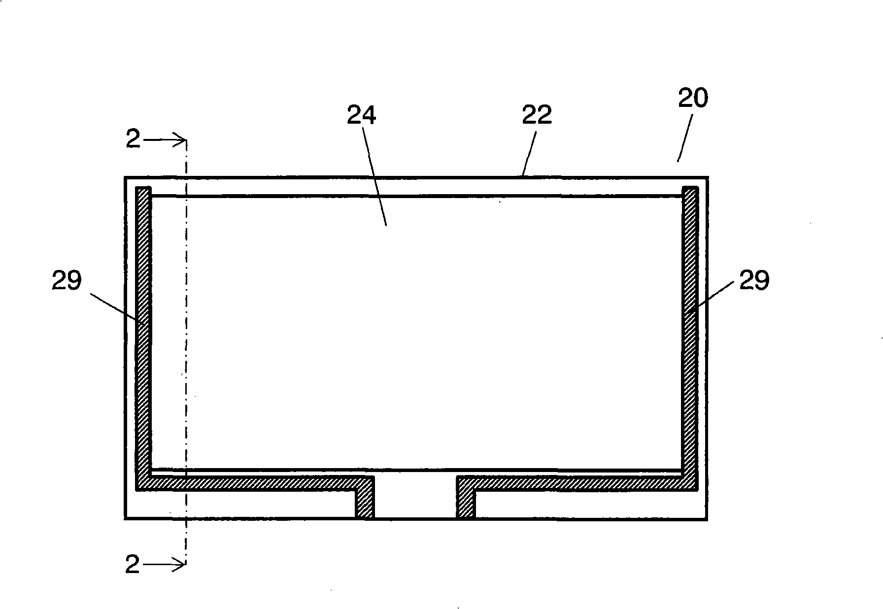
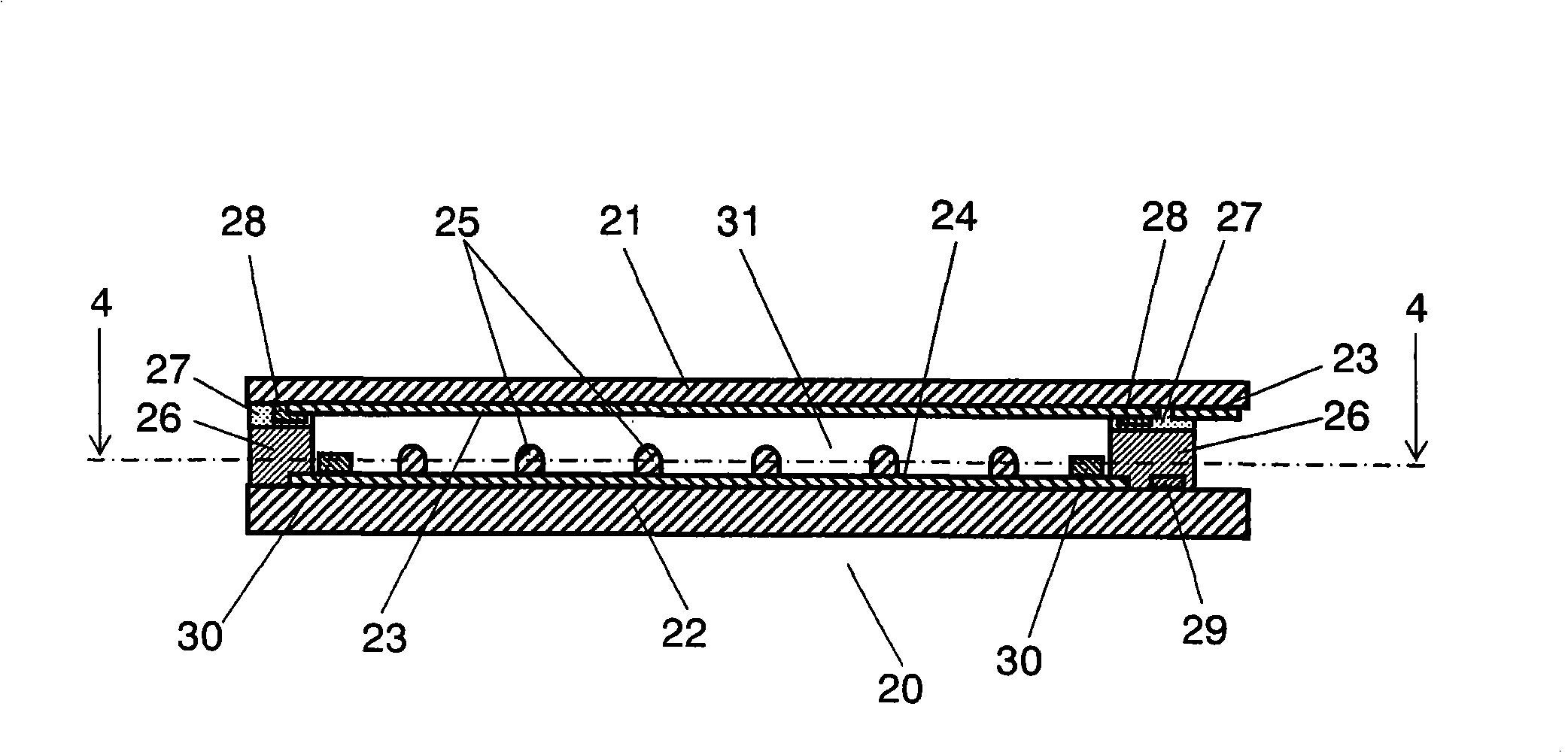
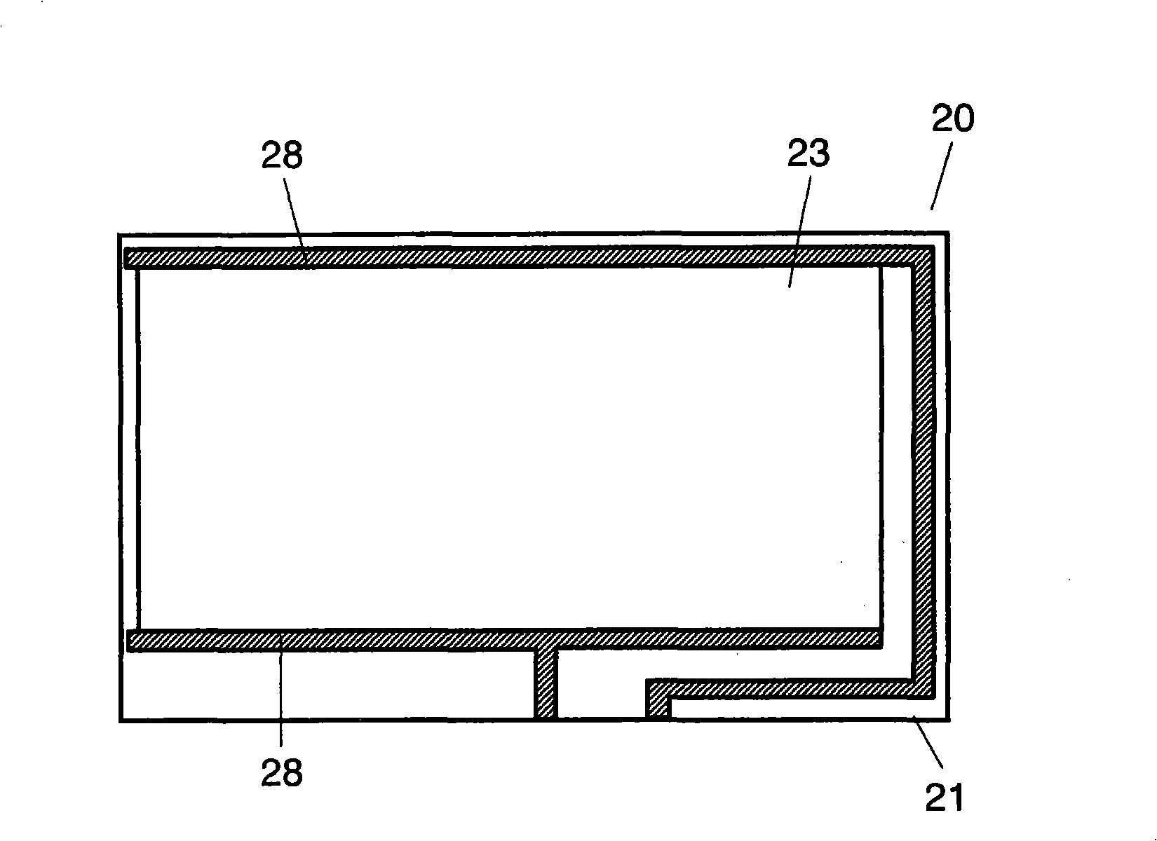
[0027] figure 1 It is a plan cross-sectional view of touch panel 20 according to the first embodiment of the present invention. figure 2 yes figure 1 A 2-2 line side cross-sectional view of touch panel 20 is shown. image 3 yes means figure 1 A schematic plan view of the upper substrate 21 of the touch panel 20 is shown. Figure 4 yes figure 2 A 4-4 cross-sectional view of the touch panel 20 is shown. Such as Figure 1 to Figure 4 As shown, the touch panel 20 is in the shape of a film, and includes a light-transmitting upper substrate 21 and a light-transmitting lower substrate 22 . The upper substrate 21 is formed of materials such as polyethylene terephthalate, polycarbonate resin, or polyether sulfone. The lower substrate 22 is formed of a material such as glass, acrylic resin, or polycarbonate resin. A light-transmitting upper conductive layer 23 is formed on the lower surface of the upper substrate 21 . The upper surface of the lower substrate 22 is similarl...

no. 2 approach

[0039] Figure 8 It is a sectional view of the touch panel 20a according to the second embodiment of the present invention. Figure 9 It is a cross-sectional view of touch panel 20a according to another aspect of the second embodiment of the present invention. In addition, in the configuration of the touch panel 20a according to the second embodiment of the present invention, the parts having the same configuration as the configuration of the touch panel 20 according to the first embodiment are denoted by the same reference numerals, and detailed description thereof will be omitted. Such as Figure 8 and Figure 9 As shown, the touch panel 20 a of the second embodiment does not have the water absorbing layer 30 . Instead of the water-absorbing layer 30 , a water-absorbing polymer material is dispersed in the point pad 35 . The water-absorbing polymer material contains, for example, any one of acrylic acid-vinyl alcohol copolymer, sodium polyacrylate, sodium acrylate-acryla...


PUM


Abstract

A touch panel includes an upper substrate, a lower substrate, an insulating spacer, a bonding layer, and a water-absorbing layer. This structure allows suppressing dew formation, so that the touch panel which is excellent in visibility and capable of positive operation is obtainable.

Description

technical field [0001] The present invention relates to a touch panel mainly used for operating various electronic devices. Background technique [0002] In recent years, along with the multi-functionalization and diversification of various electronic devices such as mobile phones and car navigation systems, electronic devices in which a light-transmitting touch panel is mounted on the front of a display element such as a liquid crystal are gradually increasing. Increase. A user of such an electronic device recognizes and selects characters, symbols or patterns displayed on some display elements on the back of the touch panel through the touch panel. At this time, press and operate the touch panel with a finger or a dedicated pen. In this way, each function of the electronic device is switched. Accordingly, a touch panel with excellent visibility and easy operation is obtained. [0003] Use the following Figure 10 Such a conventional touch panel will be described. Figu...

Claims


Application Information

Patent Timeline
Patent Type & Authority Applications(China)
IPC IPC(8): G06F3/041
CPCG06F3/045
Inventor 藤井彰二田边功二松本贤一
Owner PANASONIC CORP
Why Eureka
Try Eureka