Converter for remote signal of power switch position

A technology of power switch and converter, applied in the field of improvement of power switch structure, can solve the problems of a large number of manpower, material resources, financial resources, difficulties, and the inability of power companies to collect electricity bills in time and in full, so as to achieve the goal of maintaining interests and guaranteeing interests. Effect

Inactive Publication Date: 2009-04-15
SHENYANG POWER SUPPLY LIAONING POWER
View PDF0 Cites 0 Cited by
  • Summary
  • Abstract
  • Description
  • Claims
  • Application Information

AI Technical Summary

Problems solved by technology

[0002] The power load management system is to remotely control the customer's power switch through remote commands. The remote measurement, remote signaling and remote control of the client information are the technical measures that must be taken to ensure that the power company recovers electricity fees in a timely manner and in full to maintain the interests of the power company and power customers. However, at present, there are only a few auxiliary switches that can be remotely controlled at the customer site. For the power control of electric loads, the control of solar and lunar power, the control of factory holidays, and when the power situation of the grid tends to be tense, the system can implement the load limit issued by the superior department. It is difficult to achieve the traditional goal of "not exceeding the limit, whoever exceeds the limit, and pulling households and not pulling roads" to achieve off-peak power cuts and orderly power consumption. Therefore, power companies cannot recover electricity charges in a timely and full amount.
If the switch is transformed, a lot of manpower, material and financial resources need to be invested.

Method used


Image

  • Converter for remote signal of power switch position

Examples


Embodiment Construction

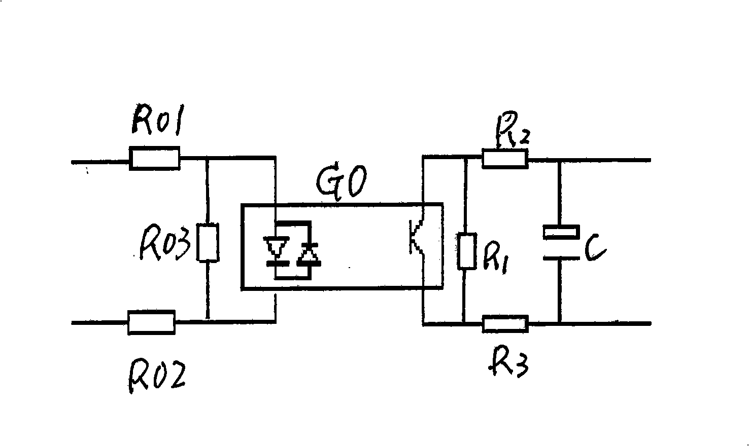
[0006] The power switch position remote signal converter is characterized in that it is composed of resistors R01, R02, R03, R1, R2, R3, capacitor C, and a bidirectional photocoupler GO, and each end of the resistors R01 and R02 is respectively connected to the bidirectional photocoupler GO. At the input end, the resistor R03 is connected in parallel to the input end of the bidirectional photocoupler GO, each end of the resistors R2 and R3 is connected to the output port of the bidirectional photocoupler GO, the resistor R1 is connected in parallel to the output port of the bidirectional photocoupler GO, and the capacitor C The two ends are respectively connected to one end of the resistors R2 and R3. Resistors R01 and R02 play the role of voltage division and current limiting, and the role of resistor R03 is to stabilize voltage, sample and protect the bidirectional photocoupler. When the power switch is in position, the two ends of the input circuit of the remote signal conve...


PUM


Abstract

The invention discloses a remote signaling converter of a power switch position, belongs to an improvement of a power switch structure, and solves the problems that the remote monitoring of power clients can not be realized and the electricity cost can not be charged in time and in full amount, which affects the economic benefit of power enterprises. The remote signaling converter of the power switch position is characterized by consisting of resistors R01, R02, R03, R1, R2 and R3, a capacitor C and a bidirectional photoelectric coupler GO; one terminal of the resistor R01 and one terminal of the resistor R02 are respectively connected with an input terminal of the bidirectional photoelectric coupler GO; the resistor R03 is connected with the input terminal of the bidirectional photoelectric coupler GO in parallel; one terminal of the resistor R2 and one terminal of the resistor R3 are respectively connected with an output terminal of the bidirectional photoelectric coupler GO; the resistor R1 is connected with the output terminal of the bidirectional photoelectric coupler GO in parallel; two terminals of the capacitor C are respectively connected with one terminal of the resistor R2 and one terminal of the resistor R3. The remote signaling converter of the power switch position has the advantages of remote metering, remote signaling and remote controlling the information of the power client side, assuring timely and full charging of the electricity cost, and maintaining the benefit of the power enterprises and the clients.

Description

Technical field: [0001] The invention is an improvement to the power switch structure. Background technique: [0002] The power load management system is to remotely control the customer's power switch through remote commands. The remote measurement, remote signaling and remote control of the client information are the technical measures that must be taken to ensure that the power company recovers electricity fees in a timely manner and in full to maintain the interests of the power company and power customers. However, at present, there are only a few auxiliary switches that can be remotely controlled at the customer site. For the power control of electric loads, the control of solar and lunar power, the control of factory holidays, and when the power situation of the grid tends to be tense, the system can implement the load limit issued by the superior department. It is difficult to achieve the traditional goal of "not exceeding the limit, whoever exceeds the limit, and pu...

Claims


Application Information

Patent Timeline
Patent Type & Authority Applications(China)
IPC IPC(8): H02J13/00H03K17/94H04M11/00
Inventor 杨勇李安平黄达王玉成黄立新庞玉晶
Owner SHENYANG POWER SUPPLY LIAONING POWER
Why Eureka
Try Eureka