Improved fan bearing set structure

A technology of fan bearing and group structure, which is applied to the components of pumping devices for elastic fluids, non-variable-capacity pumps, machines/engines, etc., can solve the problems of vibration and noise, waste, high production cost, and prevent Effects of noise and wear, increased service life, and reduced production costs

Inactive Publication Date: 2009-04-22
EVERCOOL THERMAL
View PDF0 Cites 12 Cited by
  • Summary
  • Abstract
  • Description
  • Claims
  • Application Information

AI Technical Summary

Problems solved by technology

[0003] see Figure 4 Shown is a fan bearing assembly 50 in the prior art, which is arranged between a base body 30 and an impeller 40. A shaft tube 31 protrudes from the center of the base body 30, wherein the bearing assembly 50 mainly includes a fixed block 51. A mandrel 52, two ball bearings 53, a washer 54 and a spring 55, the fixed block 51 is fixed on the opening at the bottom of the shaft tube 31, and the two ends of the mandrel 52 are respectively fixed on the fixed block 51 and the impeller 40 center, the two ball bearings 53 spacing rings are arranged on the mandrel 52 and are located in the shaft tube 31, the gasket 54 is arranged on one end of the mandrel 52 and is located between a ball bearing 53 and the fixed block 51, the spring The ring 55 is set at the other end of the mandrel 52 and is supported between another ball bearing 53 and the impeller 40, so as to push the inner ring body of the ball bearing 53 and prevent the steel ball inside from being caught between the inner ring body and the outer ring body. However, this kind of bearing group 50 with two ball bearings 53 can evenly distribute the force of the entire spindle 52 on the two ball bearings 53, so as to reduce the stress on the internal steel balls and increase Its service life, but also because of this, makes its manufacturing cost high, and two ball bearings 53 also easily make its axle center not on the same straight line because of manufacturing error, cause mandrel 52 to vibrate, in addition, although spring 55 pushes the top The force of the inner ring body of the ball bearing 53 and the suction force between the magnetic pole surface and the permanent magnet will pull the impeller 40 and the mandrel 52 to move toward the seat body 30, but the force of the spring 55 pushing the impeller 40 and the force generated when the impeller 40 rotates The buoyancy force will pull the impeller 40 and the mandrel 52 to move away from the base body 30, that is, the inner ring body of the ball bearing 53 is constantly moving relative to the outer ring body, causing the balls to bounce inside, even making noise, causing wear and tear. Make the mandrel 52 damaged due to the shear force
[0004] see further Figure 5 As shown, in view of the above-mentioned shortcomings that the axes of the two ball bearings 53 are not on the same straight line, someone has designed another bearing set 60 in which one of the ball bearings 53 is replaced by a bushing 61. It is expected that in addition to In addition to solving the problems of vibration and noise, on the other hand, because the price of the shaft sleeve 61 is cheaper than that of the ball bearing 53, and its service life is also longer, it is hoped that this can be used to solve the problem of having two ball bearings 53 that are expensive , and the shortcomings of vibration, noise, and shear force acting on the mandrel 52 due to their axes not being on the same straight line, while increasing the service life of the bearing set 60, it is only in fact that when the ball bearing 53 is broken , although the shaft sleeve 61 is not broken, the ball bearing 53 in it cannot be replaced separately to continue to use, so the service life is not only not increased, but it will cause waste, and the suction force between the magnetic pole surface and the permanent magnet is still unable to resist the impeller 40. Due to the buoyancy generated during rotation, the balls in the mandrel 52, the impeller 40 and the ball bearing 53 still cannot rotate stably, and the end of the mandrel 52 arranged on the fixed block 51 will still be damaged by shear force, so the prior art There is still room for further improvement in the fan bearing set

Method used


Image

  • Improved fan bearing set structure
  • Improved fan bearing set structure
  • Improved fan bearing set structure

Examples


Embodiment Construction

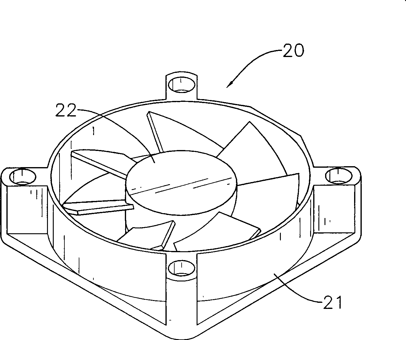
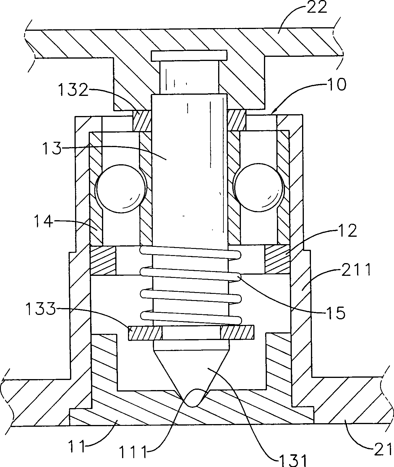
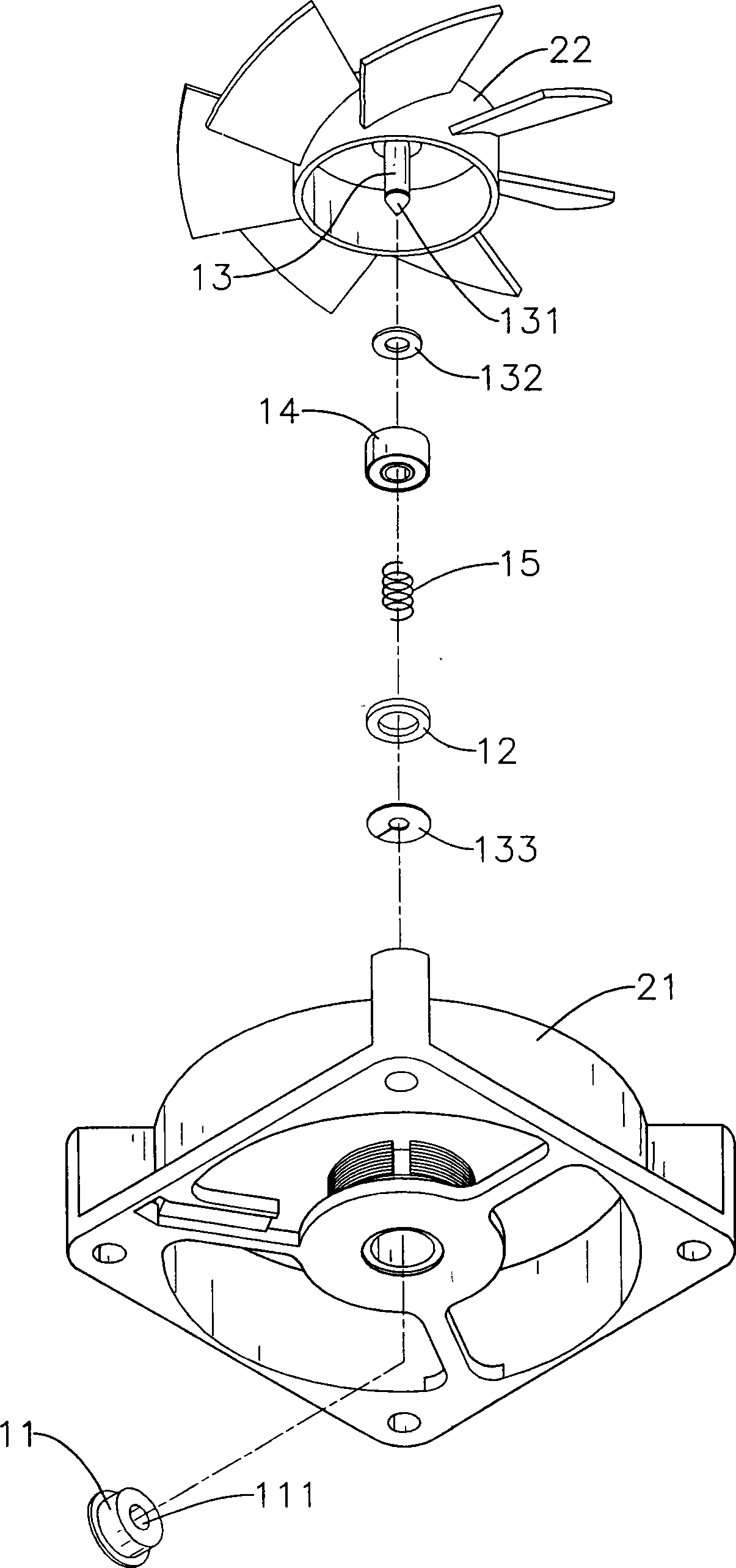
[0033] see figure 1 and figure 2 As shown, the present invention is applied to a fan 20. The fan 20 includes a base 21 and an impeller 22. A shaft tube 211 protrudes from the center of the base 21. Openings are provided at both ends of the shaft tube 211. Among them, The improved fan bearing assembly 10 of the present invention is installed between the shaft tube 211 of the seat body 21 and the impeller 22, and includes a fixed block 11, a positioning ring 12, a mandrel 13, a ball bearing 14 and a spring 15, in:

[0034] The fixed block 11 is a wear-resistant pad, and its cover is fixed on the opening at the bottom of the shaft tube 211, and a tapered groove 111 is concavely formed in the center of its inner surface;

[0035] The positioning ring 12 is fixed on the inner wall of the shaft tube 211;

[0036] The mandrel 13 axially passes through the opening in the shaft tube 211, one end of which is fixed at the center of the impeller 22, and the other end is formed into a...


PUM


Abstract

The invention discloses an improved structure of a fan bearing pack. The fan bearing pack is arranged between a shaft tube of a base of a fan and an impeller and comprises a fixing block and a spindle, wherein the fixing block is provided with a cone-shaped groove in the middle, and the spindle is inserted into the shaft tube. One end of the spindle is fixedly arranged on the impeller and the other end of the spindle is formed into a cone-shaped end which can pivot in the groove of the fixing bloc. The spindle is provided with a ball bearing, a lower gasket, a spring clamped and supported between the ball bearing and the lower gasket. The fan bearing pack has advantages of low manufacture cost, stable rotation, reduction of vibration, noise and shearing force applied on the spindle and improved service life.

Description

technical field [0001] The invention relates to an improved fan bearing set structure. Background technique [0002] The design of the generally known fan mainly includes a base body, an impeller and a bearing group. A shaft tube protrudes from the center of the base body, and a circuit board and a stator are arranged on the outer ring of the base body. The stator has several magnetic pole surfaces and is wound There is a coil, the two ends of which are electrically connected to the circuit board. The impeller includes a casing and several fan blades that are arranged on the outer surface of the casing. The inner surface of the casing is provided with a permanent magnet, which corresponds to the magnetic pole surface of the stator. , by electrifying the circuit board, the coil of the stator makes the magnetic pole surface generate magnetism, and then uses the magnetic attraction and repulsion between the magnetic pole surface and the permanent magnet to drive the impeller to...

Claims


Application Information

Patent Timeline
Patent Type & Authority Applications(China)
IPC IPC(8): F04D29/056
Inventor 陈乾昌
Owner EVERCOOL THERMAL
Why Eureka
Try Eureka