Gas transverse uniform output device

An output device, horizontal technology, applied in the direction of gas fuel burner, combustion method, combustion type, etc.

Active Publication Date: 2010-11-03
上海誉辉化工有限公司
View PDF8 Cites 0 Cited by
  • Summary
  • Abstract
  • Description
  • Claims
  • Application Information

AI Technical Summary

Problems solved by technology

[0002] Traditional cutting devices, no matter EDM cutting machine, flame cutting machine, or laser cutting machine, the nozzles of the cutting machine are round beams, so it is bound to Regardless of whether the electric spark, flame or laser comes out of the nozzle, it always looks like a similar flame shape (beam), divided into inner flame (incomplete combustion part), outer flame (full combustion part), and the resulting problems are: cutting Constantly adjust the distance between the flame and the object to be cut so that the outer flame can fully contact the object to be cut, resulting in inconvenient construction; due to the extension of the construction time, it is a great waste of resources such as gas; if cutting a large area of ​​objects , the beam-shaped cutting machine is obviously not efficient
[0011] However, in this type of device, whether it is spot cutting or wire cutting, the flame, laser, and plasma nozzles are all spray guns, and it is inevitable that similar flames will appear. The temperature difference between the inner and outer flames and the divergence of the flames cause heat energy loss. In addition, the inconsistency of the flame height and the movable cutting of the nozzle reduce the use efficiency
[0012]The cause of these defects is that the pressure is not uniform across the gas outlet

Method used


Image

  • Gas transverse uniform output device
  • Gas transverse uniform output device
  • Gas transverse uniform output device

Examples


Embodiment approach

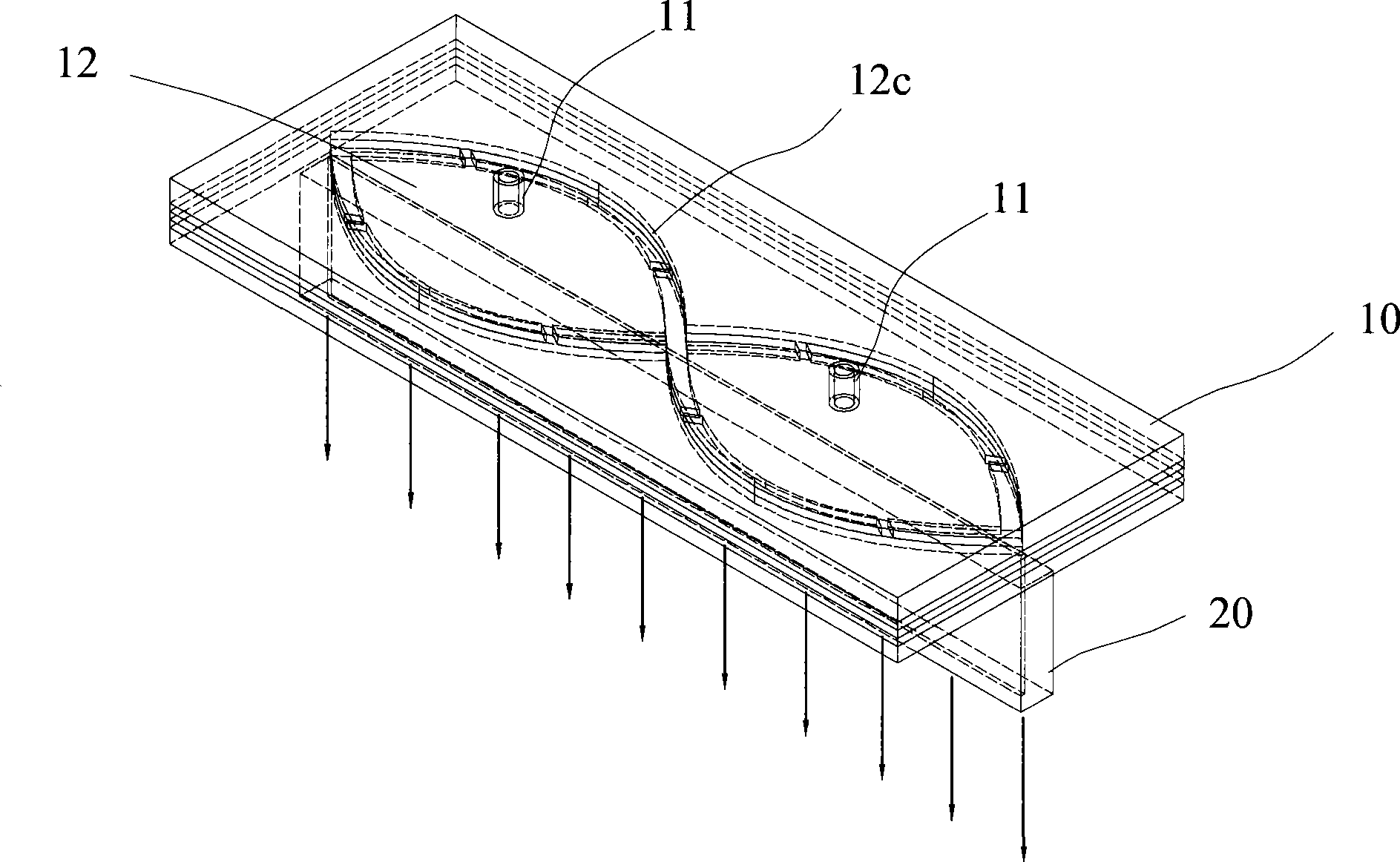
[0036] Such as Figure 1-3 Shown is the first embodiment of the gas horizontal uniform output device of the present invention. The gas horizontal uniform output device includes a gas distribution part 10 and a nozzle part 20 .

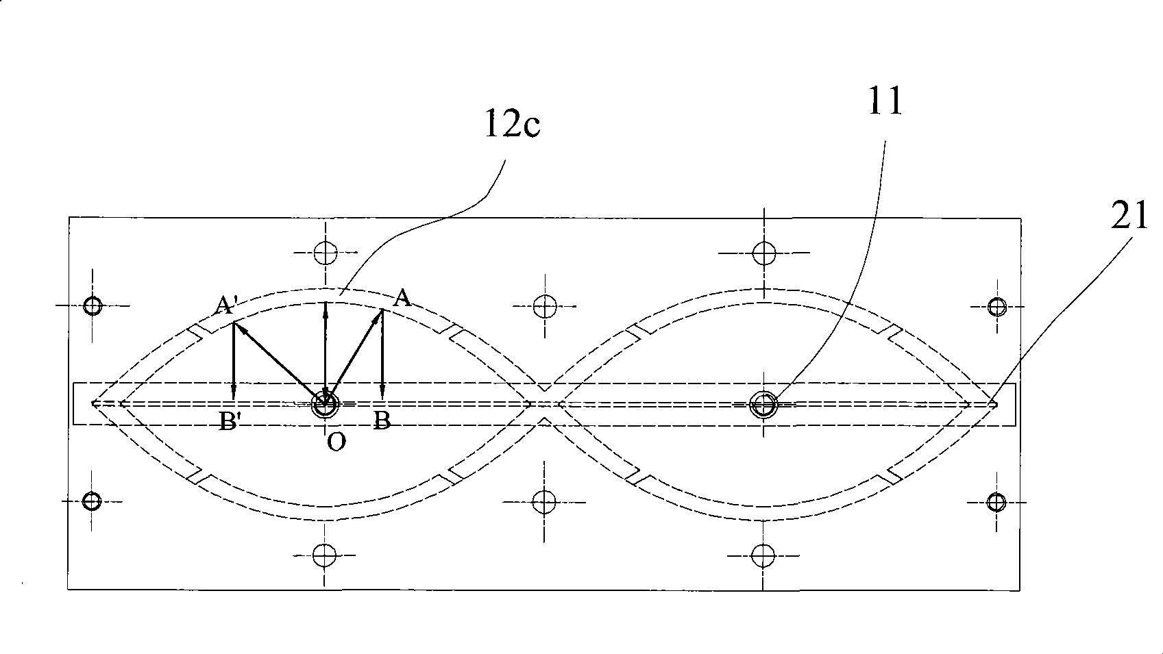
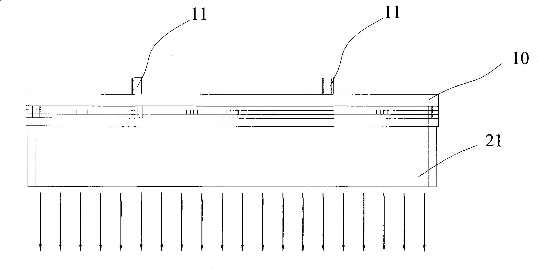
[0037] The top surface of the distribution part 10 is provided with an air inlet 11 , and the bottom surface is connected with the nozzle part 20 . The spout part 20 is located on the bottom surface of the distribution part 10 , its length is substantially the same as that of the distribution part 10 , and its width is much smaller than that of the distribution part 10 . A slit 21 is formed in the nozzle part 20 along the longitudinal direction. In this embodiment, the positions of the air inlet 11 and the upper end of the slit 21 in the vertical direction correspond to each other.

[0038] The gas enters the distribution part 10 from the air inlet 11 , passes through the gas channel 12 formed in the distribution part 10 , and flows to the slit 21 i...


PUM


Abstract

The invention relates to a device used for transversely and evenly outputting gas, which comprises a distribution part and a spout part, wherein, the distribution part includes at least one air inlet that is communicated with a flow passage formed inside the distribution part; the spout part is arranged at the bottom side of the distribution part and is internally provided with a narrow slit which has the fixed size and is communicated with the flow passage; furthermore, the gas flow paths around the position from the air inlet through the flow passage to the narrow slit are fixed value. By adopting the structure of the invention, the paths of the gas from the air inlet to the narrow slit are consistent in terms of theory, or the path distance difference is controlled within the error band according to the needs, so that the gas sprayed out from the spout part keeps uniform pressure along the length direction. In addition, the device has the advantages of simple structure, convenient processing and lower manufacturing cost.

Description

technical field [0001] The invention relates to a gas horizontally uniform output device, in particular to a gas output device which can evenly distribute gas from laterally continuous nozzles to achieve uniformity and stability. Background technique [0002] Traditional cutting devices, no matter EDM cutting machine, flame cutting machine, or laser cutting machine, the nozzles of the cutting machine are all in the shape of round beams, so it is bound to appear that no matter whether the electric spark, flame or laser comes out from the nozzle, it always looks like Similar flame shape (beam shape), divided into inner flame (incomplete combustion part) and outer flame (full combustion part), the resulting problems are: when cutting, constantly adjust the distance between the flame and the object to be cut so that the outer flame Being able to fully contact the object to be cut makes construction inconvenient; due to the extension of construction time, it is a great waste of r...

Claims


Application Information

Patent Timeline
Patent Type & Authority Patents(China)
IPC IPC(8): F23D14/38F23D14/58
Inventor 王兴南
Owner 上海誉辉化工有限公司
Why Eureka
Try Eureka