Air source heat pump phase-change energy storage defrosting system with super cooling effect

An air-source heat pump and phase-change energy storage technology, which is applied to compressors with reversible cycles, heat pumps, refrigerators, etc., can solve the problems of long defrosting time and insufficient defrosting energy sources, and achieves low cost and simple structure. , the effect of improving comfort

Inactive Publication Date: 2009-04-22
HARBIN INST OF TECH
View PDF1 Cites 36 Cited by
  • Summary
  • Abstract
  • Description
  • Claims
  • Application Information

AI Technical Summary

Problems solved by technology

[0004] The purpose of the present invention is to provide an air source heat pump phase-change energy storage defrosting system with supercooling effect to solve the problem that when the air source heat pump unit adopts the existing defrosting method for defrosting, there is no low-level heat source in the defrosting process. , resulting in insufficient defrosting energy source and longer defrosting time

Method used


Image

  • Air source heat pump phase-change energy storage defrosting system with super cooling effect
  • Air source heat pump phase-change energy storage defrosting system with super cooling effect
  • Air source heat pump phase-change energy storage defrosting system with super cooling effect

Examples


specific Embodiment approach 1

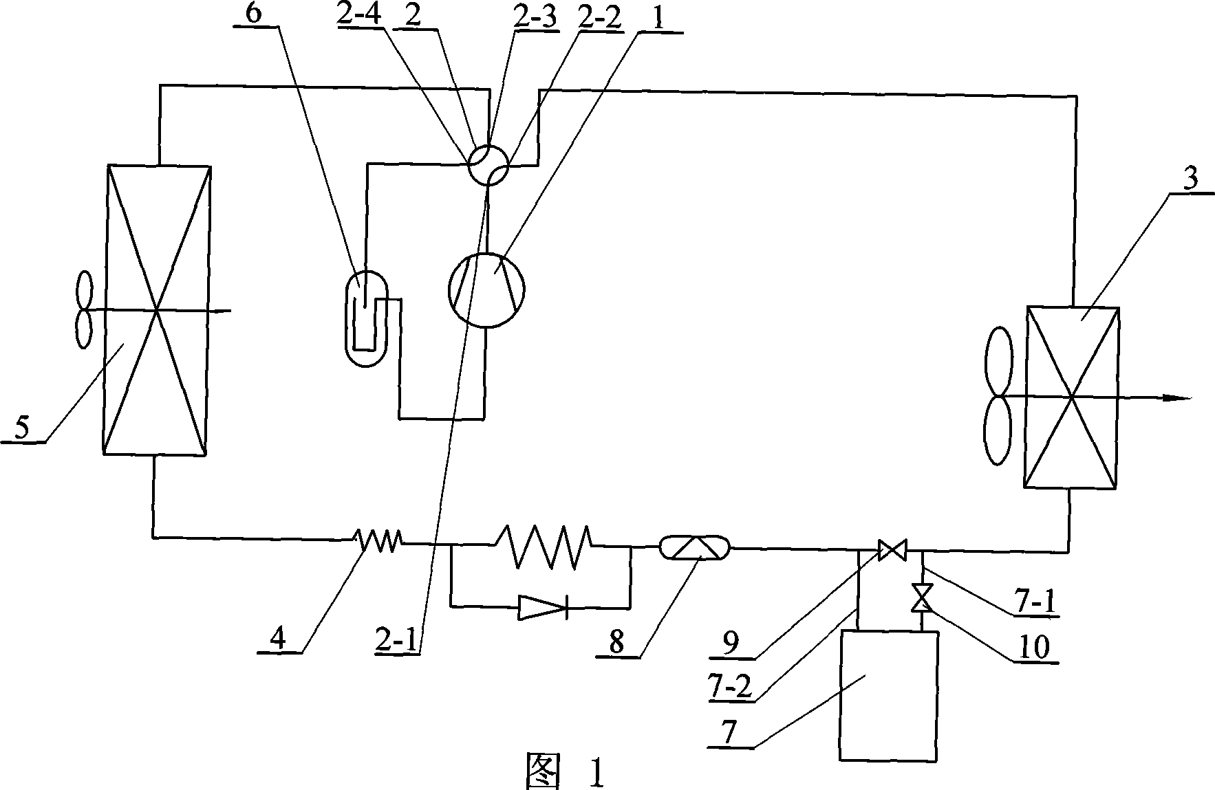
[0008] Specific Embodiment 1: This embodiment is described in conjunction with FIG. 1. The system of this embodiment includes a compressor 1, a four-way reversing valve 2, an indoor heat exchanger 3, a capillary tube 4, an outdoor heat exchanger 5, and a gas-liquid separator 6 and dry filter 8; between the output end of the compressor 1 and the first valve port 2-1 of the four-way reversing valve 2, between the input end of the compressor 1 and the output end of the gas-liquid separator 6, Between the input end of the gas-liquid separator 6 and the third valve port 2-3 of the four-way reversing valve 2, between the fourth valve port 2-4 of the four-way reversing valve 2 and the outdoor heat exchanger 5, outdoor Between the heat exchanger 5 and the capillary 4, between the capillary 4 and the drier filter 8, between the drier filter 8 and the indoor heat exchanger 3, and between the indoor heat exchanger 3 and the second valve port of the four-way reversing valve 2 2-2 are resp...

specific Embodiment approach 2

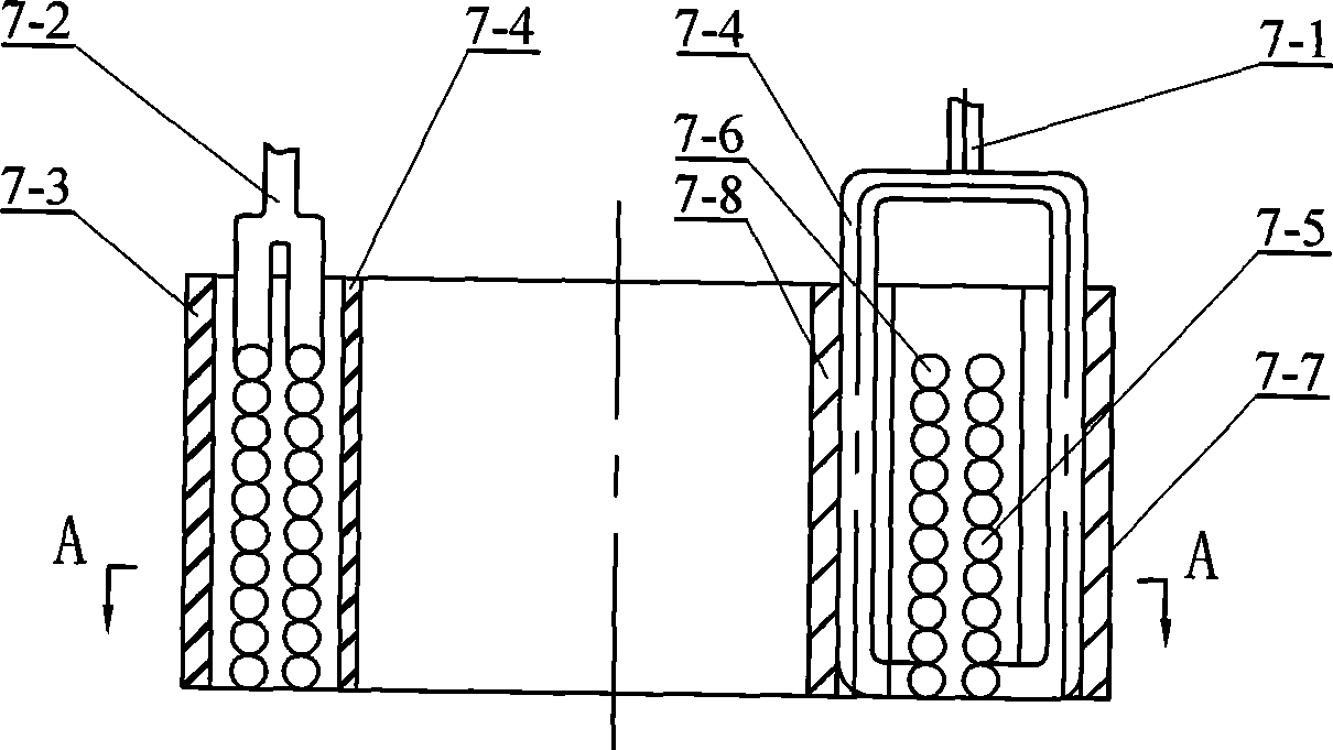
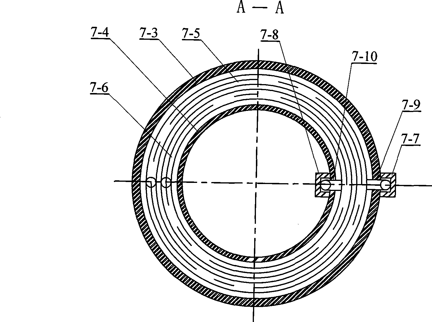
[0009] Specific implementation mode two: combination figure 2 with image 3 Describe this embodiment, the energy storage heat exchanger 7 of this embodiment consists of an outer casing 7-3, an inner casing 7-4, an outer coil 7-5, an inner coil 7-6, and an outer protective pipe groove 7-7 , the inner protective pipe groove 7-8, the inlet and outlet main pipe 7-1 and the inlet and outlet main pipe 7-2; the outer casing 7-3 and the inner casing 7-4 are nested together, and the inner coil 7-6 is arranged Between the outer casing 7-3 and the inner casing 7-4 and set on the inner casing 7-4, the outer coil 7-5 is arranged between the inner coil 7-6 and the outer casing 7-3 and is set on the On the inner coil 7-6, the outer long hole 7-9 is arranged on the pipe wall of the outer pipe 7-3 along the length direction, and the outer long hole 7-9 of the inner pipe 7-4 is connected with the outer long hole 7-9 of the outer pipe 7-3. The corresponding position is provided with an inner l...

specific Embodiment approach 3

[0011] Specific embodiment three: in combination with Fig. 4 and Figure 5 To illustrate this embodiment, the energy storage heat exchanger 7 of this embodiment is composed of a shell 7-11, a heat exchange tube bundle 7-12, two tube sheets 7-13, an inlet and outlet main pipe 7-1, and an inlet and outlet main pipe 7-2 ; The two tube sheets 7-13 are fixed in the shell 7-11, the heat exchange tube bundle 7-12 is arranged in the shell 7-11, and the two ends of the heat exchange tube bundle 7-12 are fixed in the two tube sheets In the tube hole of 7-13, one end of the inlet and outlet main pipe 7-1 is connected with one end of the housing 7-11, one end of the inlet and outlet main pipe 7-2 is connected with the other end of the housing 7-11, and the end of the housing 7-11 A phase change material injection port 7-14 is provided on the upper end near the inlet and outlet main pipe 7-1, and a phase change material outlet 7-15 is provided on the lower end of the housing 7-11 near the ...


PUM


Abstract

The invention relates to an air source heat pump phase change energy storage defrosting system with super cooling action. When the existing defrosting mode is used for defrosting by an air source heat pump unit, no low level heat source exists during the defrosting process, thus leading to the problems that the defrosting energy source is insufficient and the defrosting time is longer. Pipelines are used for connection between a compressor and a four-way reversing valve, between the compressor and a gas-liquid separator, between the gas-liquid separator and the four-way reversing valve, between the four-way reversing valve and an outdoor heat exchanger, between the outdoor heat exchanger and a capillary tube, between the capillary tube and a device for drying and filtering, between the device for drying and filtering and an indoor heat exchanger, and between the indoor heat exchanger and the four-way reversing valve respectively; and an energy storage heat exchanger is arranged on the pipeline between the device for drying and filtering and the indoor heat exchanger. In the invention, the supercooling is finished by a refrigerant and the phase change material uses the refrigerant to store afterheat, thus improving the performance of the unit, realizing the planeshift of energy, and providing sufficient low level heat source for defrosting.

Description

technical field [0001] The invention relates to an air source heat pump phase change energy storage defrosting system. Background technique [0002] As an energy-saving and environment-friendly heating method, air source heat pump has received more and more attention. However, during operation, there is frosting on the outdoor heat exchanger of the unit. The existence of the frost layer seriously affects the heating performance of the unit. Therefore, it is necessary to remove the frost layer in time. How to achieve timely and effective defrosting has become an urgent research problem. There are many existing defrosting methods, but they all have different degrees of problems. In summary, there are mainly the following problems: 1. Natural defrosting method, the compressor needs to be interrupted during defrosting, and the outdoor air temperature is required to be higher than 2-3 °C Only when it can run, the limitation is big. 2. The electric heating defrosting method c...

Claims


Application Information

Patent Timeline
Patent Type & Authority Applications(China)
IPC IPC(8): F25B47/02F25B13/00F25B30/06F28D20/02
CPCY02E60/145Y02E60/14
Inventor 姜益强姚杨马最良董建锴
Owner HARBIN INST OF TECH
Why Eureka
Try Eureka