
Display device and method of manufacturing display device

A technology for a display device and a manufacturing method, applied in identification devices, semiconductor/solid-state device manufacturing, optics, etc., can solve the problems of increased manufacturing man-hours, insufficient, complex structures, etc., and achieve reduced cut-off current, low cost, and simple structure Effect

Active Publication Date: 2009-04-22
JAPAN DISPLAY INC +1
View PDF1 Cites 6 Cited by
  • Summary
  • Abstract
  • Description
  • Claims
  • Application Information

AI Technical Summary

Problems solved by technology

Therefore, there is a problem that the structure becomes complicated, resulting in an increase in manufacturing man-hours.
Only by relaxing the electric field in the vertical direction by the semiconductor layer, the effect of reducing the off-state current is not sufficient

Method used


Image

  • Display device and method of manufacturing display device
  • Display device and method of manufacturing display device
  • Display device and method of manufacturing display device

Examples


Embodiment Construction

[0036] Hereinafter, the display device of the present invention will be described in detail with reference to the drawings.

[0037] In all the drawings for explaining the embodiments, components having the same functions are denoted by the same reference numerals, and detailed description thereof will be omitted.

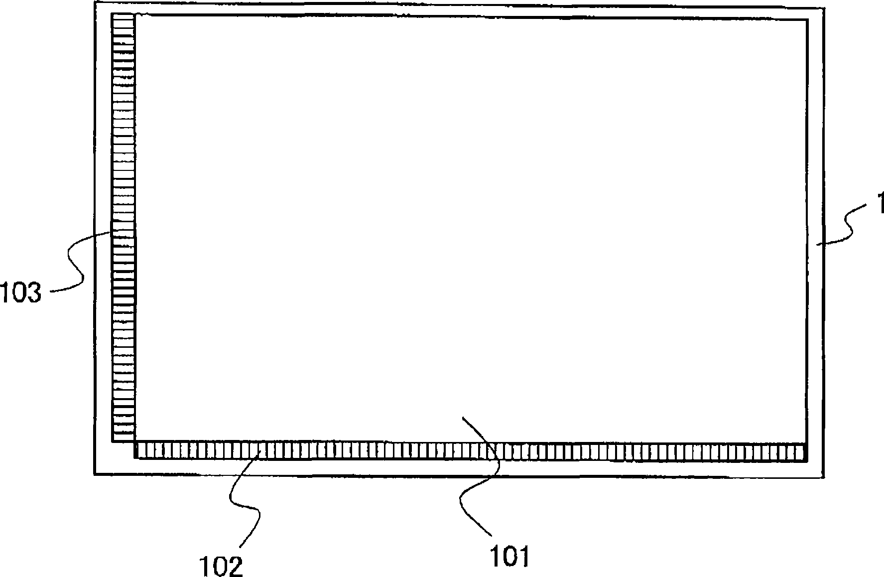
[0038] figure 1 It is a diagram showing an insulating substrate on which a thin film transistor is formed, constituting the display device of the present invention. The insulating substrate 1 is composed of, for example, a glass substrate using glass as a material.

[0039] A display region 101 is formed on the insulating substrate 1 . A plurality of pixels are formed in the display area. Drive circuits such as an RGB switch 102, a shift register 103, and the like are formed in a peripheral area outside the display area. These drive circuits are built on the insulating substrate 1 .

[0040] The pixels in the display area 101 use amorphous silicon thin film tr...


PUM

PropertyMeasurementUnit
thicknessaaaaaaaaaa
thicknessaaaaaaaaaa
thicknessaaaaaaaaaa

Abstract

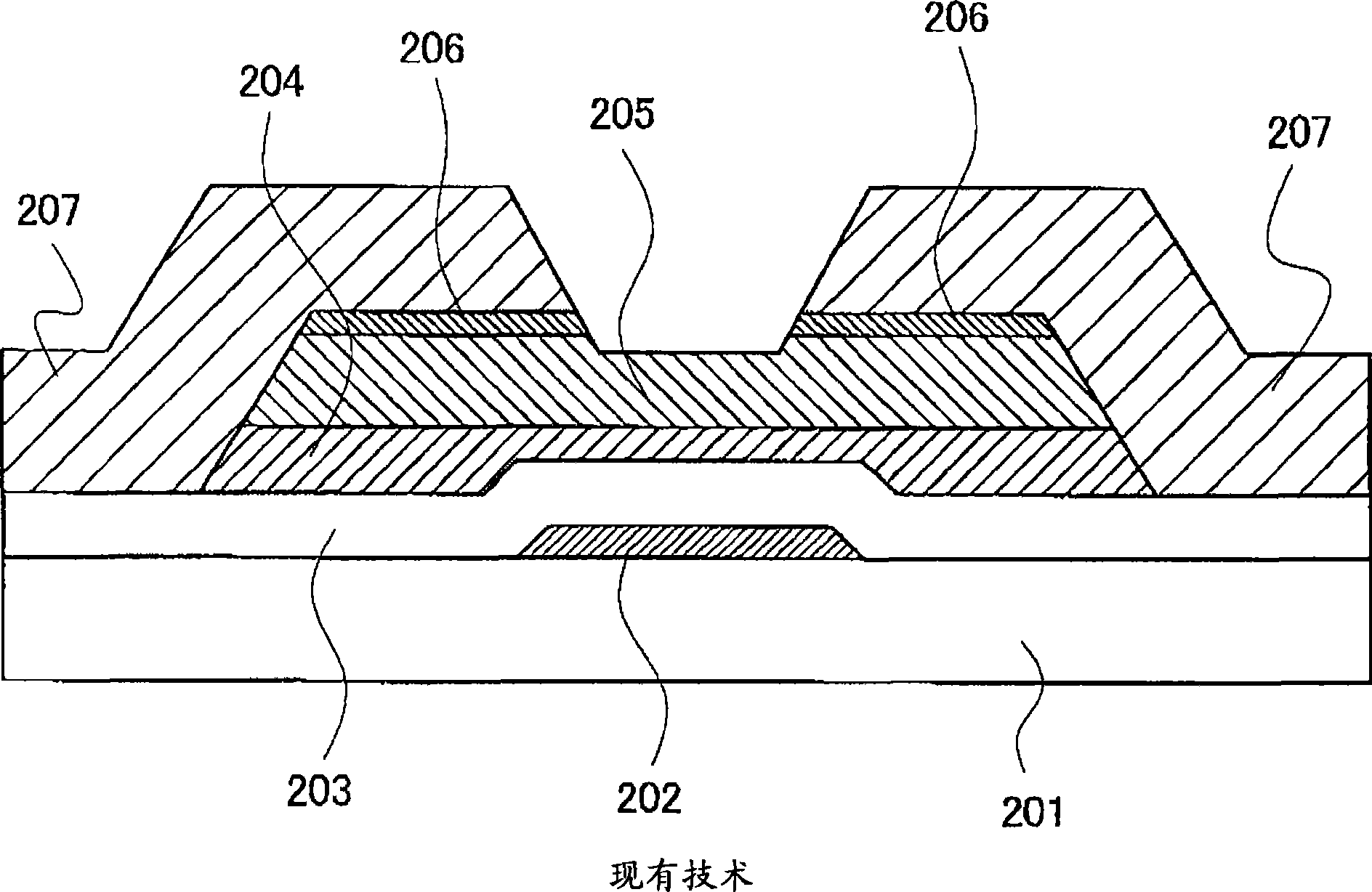
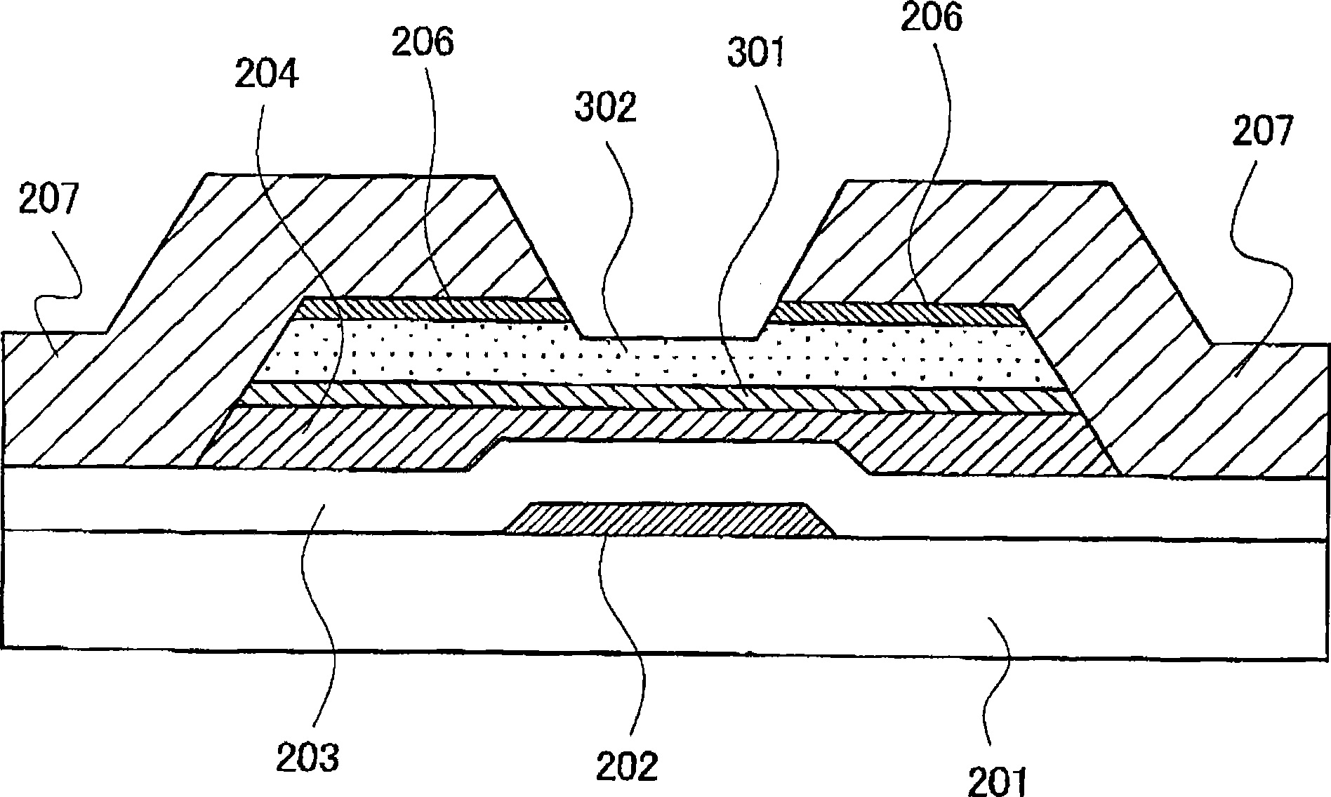
Provided is a display device, including a polysilicon thin film transistor, which achieves a reduction of an off current with a simple configuration and with only a slight increase in a number of processes. A display device includes: an insulating substrate, and a thin film transistor formed on the insulating substrate, wherein a semiconductor layer of the thin film transistor has a polysilicon layer, a first amorphous silicon layer formed above the polysilicon layer, and a second amorphous silicon layer formed above the first amorphous silicon layer.

Description

technical field [0001] The present invention relates to display devices, and more particularly to display devices with thin film transistors. Background technique [0002] Such a display device has a plurality of pixels arranged in a matrix in its display portion, and the thin film transistors of each pixel are turned on by a scan signal supplied through a gate signal line to sequentially select each pixel column, corresponding to the selection timing. The ground supplies an image signal to each pixel of the pixel column through a drain signal line, wherein the drain signal line is shared with pixels opposite to other pixel columns. [0003] In some cases, a drive circuit for driving the display device is formed around the display area formed by the aggregate of the above-mentioned pixels, and the drive circuit also includes a thin film transistor. [0004] As the above thin film transistor, a thin film transistor having a semiconductor layer formed of amorphous silicon has...

Claims


Application Information

Patent Timeline
Patent Type & Authority Applications(China)
IPC IPC(8): H01L29/786H01L27/12H01L21/336H01L21/20H01L21/84G02F1/1368G09F9/30
CPCH01L27/1251H01L29/66765H01L29/78696H01L27/1229
Inventor 三宅秀和海东拓生栗谷川武宫泽敏夫
Owner JAPAN DISPLAY INC
Learn More