Riata for elevator
A rope and elevator technology, used in textile cables, textiles and papermaking, elevators, etc., can solve the problems of sheave wear, increased wire hardness, shortened rope life, etc., to prolong life, prevent bending stress from increasing, and reduce diameter small effect
- Summary
- Abstract
- Description
- Claims
- Application Information
AI Technical Summary
Problems solved by technology
Method used
Image
Examples
Embodiment approach 1
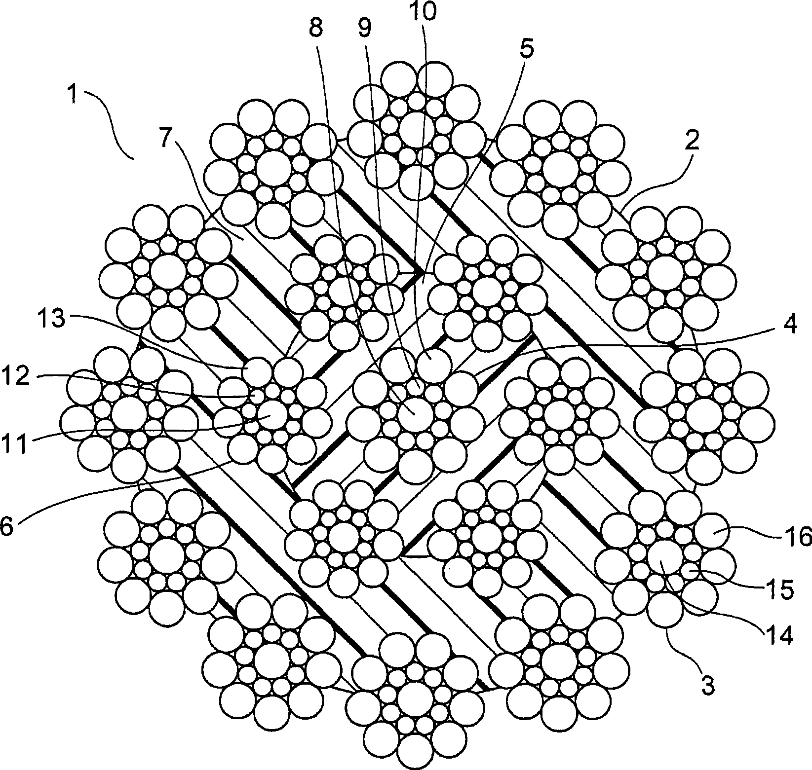
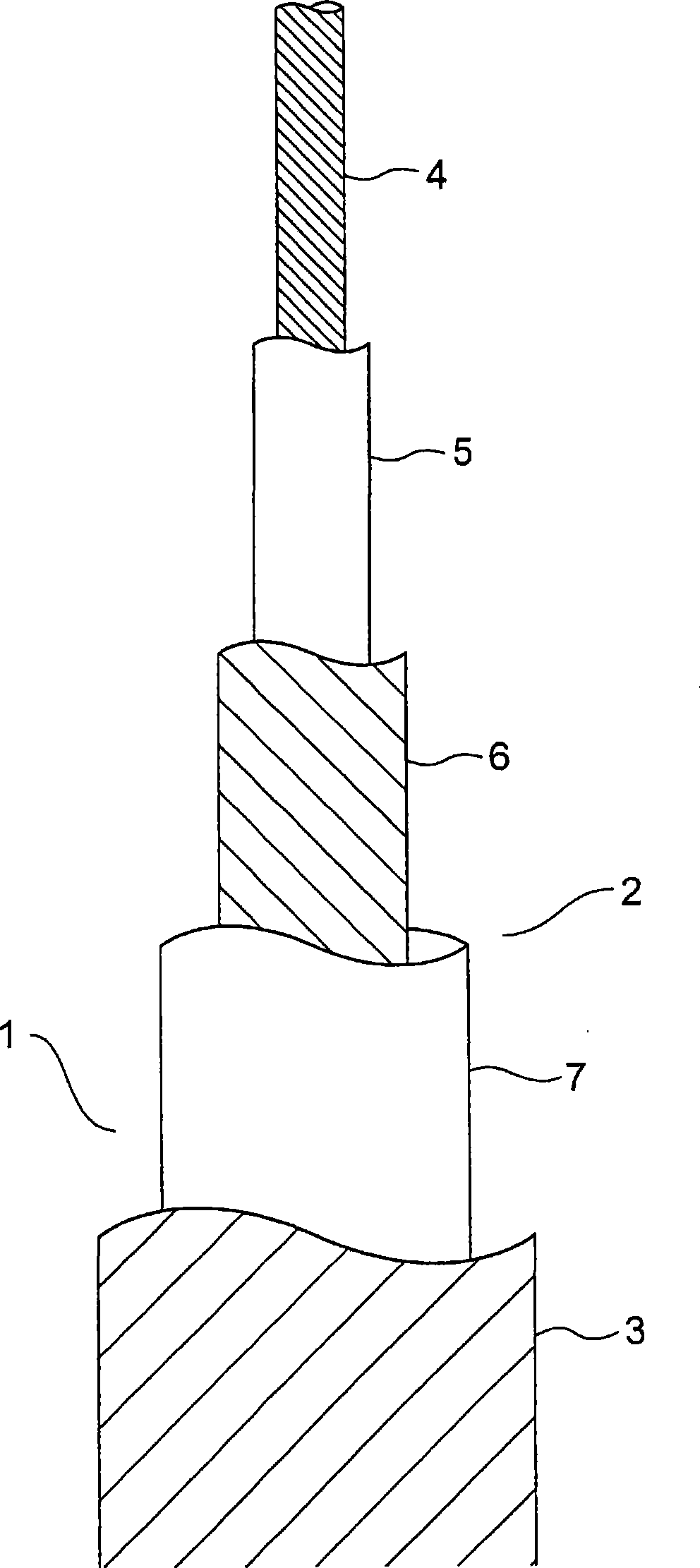
[0017] figure 1 It is a sectional view showing the elevator rope according to Embodiment 1 of the present invention. also, figure 2 will be figure 1 A schematic side view of the elevator in , with a section of the rope cut away. In the drawing, an elevator rope 1 has a core rope 2 and twelve outer layer strands 3 provided on the outer periphery of the core rope 2 .
[0018] The core rope 2 has: a core rope 4; a resin-made inner layer covering body 5 covering the outer periphery of the core rope 4; six inner layer strands 6 provided on the outer peripheral portion of the inner layer covering body 5; And the outer layer covering body 7, which uniformly covers the core rope 4, the inner layer covering body 5 and each inner layer sub-rope 6.
[0019] The core rope 4 is arranged at the center of the core rope 2 . Further, in the core rope 4 , there are provided a core rope center portion, a first wire layer surrounding the outer periphery of the core rope center portion, and ...
Embodiment approach 2
[0053] Figure 4 It is a cross-sectional view showing an elevator rope according to Embodiment 2 of the present invention. In the figure, when the core rope 4 is compressed from the outer periphery, the cross-sectional shape of the wires 8 to 10 of the core rope 4 is distorted. In addition, when the inner layer strands 6 are compressed from the outer periphery, the cross-sectional shapes of the wires 11 to 13 of the inner layer strands 6 are distorted. In addition, when the outer layer strand 3 is compressed from the outer periphery, the cross-sectional shape of the wires 14 to 16 of the outer layer strand 3 is distorted. That is, by compressing the core rope 4 , the inner layer strand 6 , and the outer layer strand 3 from the outer periphery, the shapes of the cross-sections of the respective wires of the core rope 4 , the inner layer strand 6 , and the outer layer strand 3 are distorted. Other structures are the same as those in Embodiment 1.
[0054] In such an elevator ...
Embodiment approach 3
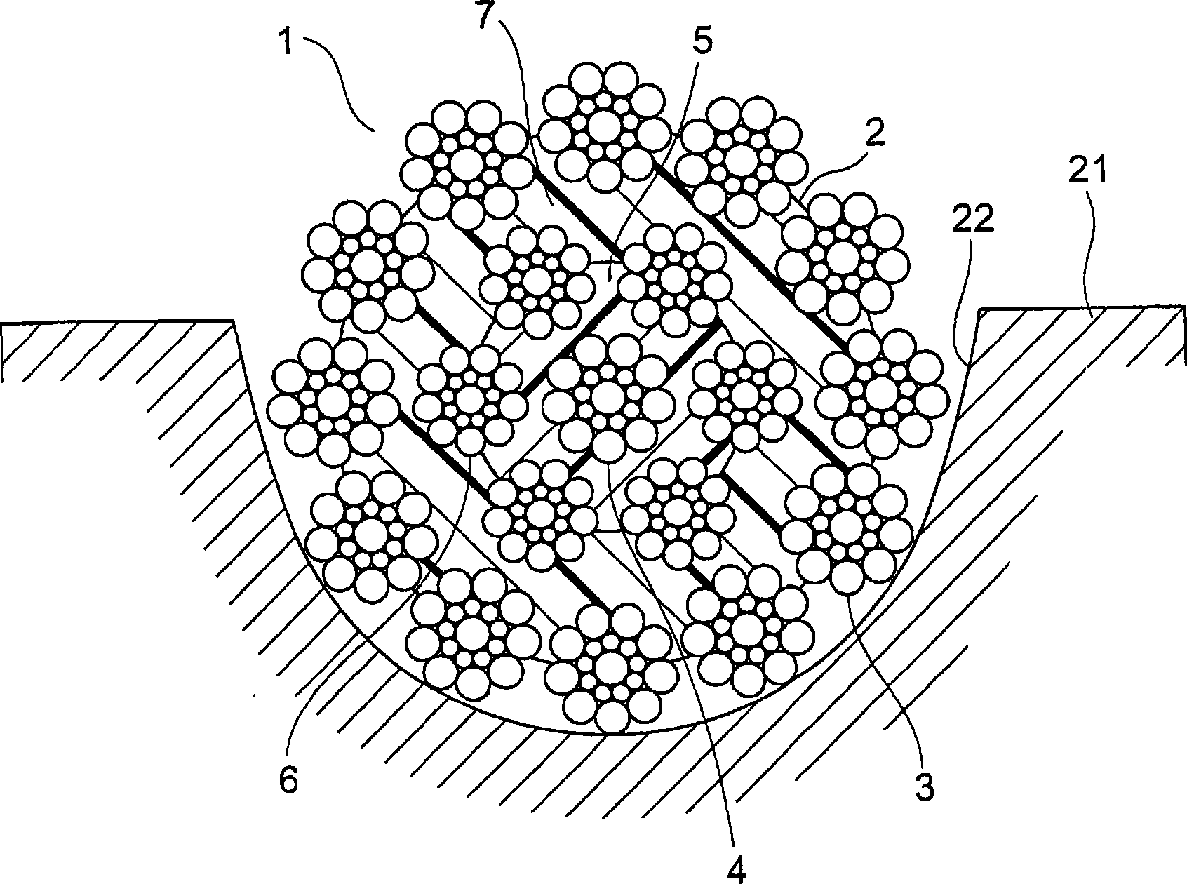
[0056] Figure 5 It is a cross-sectional view showing an elevator rope according to Embodiment 3 of the present invention. In the figure, when the core rope 4 is compressed from the outer periphery, the cross-sectional shape of the wires 8 to 10 of the core rope 4 is distorted. In addition, when the inner layer strands 6 are compressed from the outer periphery, the cross-sectional shapes of the wires 11 to 13 of the inner layer strands 6 are distorted.
[0057] The cross-sectional shape of the wires 14 to 16 of the outer layer strand 3 is not distorted, but has the same cross-sectional shape as that of the wires 14 to 16 in Embodiment 1 (that is, substantially circular). Thus, the gap between the wires 14 to 16 of the outer layer strand 3 becomes larger than the gap between the wires 8 to 10 of the core rope 4 and the gap between the wires 11 to 13 of the inner layer strand 6 . .
[0058] That is, by only compressing the core rope 4 and the inner layer rope 6 among the core...
PUM
 Abstract
Description
Claims
Application Information
 - R&D
- Intellectual Property
- Life Sciences
- Materials
- Tech Scout
- Unparalleled Data Quality
- Higher Quality Content
- 60% Fewer Hallucinations
Browse by: Latest US Patents, China's latest patents, Technical Efficacy Thesaurus, Application Domain, Technology Topic, Popular Technical Reports.
© 2025 PatSnap. All rights reserved.Legal|Privacy policy|Modern Slavery Act Transparency Statement|Sitemap|About US| Contact US: help@patsnap.com


