Lathe automatic feeding device for axle machining

An automatic feeding and lathe technology, which is applied to metal processing equipment, automatic/semi-automatic lathes, turning equipment, etc., can solve the problems of insufficient equipment utilization, high scrapping, and long time consumption, and achieve labor cost reduction, reasonable overall structure, Easy to install and use

Inactive Publication Date: 2009-04-29
NINGBO XIECHENG POWER TOOLS CO LTD
View PDF0 Cites 10 Cited by
  • Summary
  • Abstract
  • Description
  • Claims
  • Application Information

AI Technical Summary

Problems solved by technology

[0013] Since the loading and unloading of existing lathes are all manual operations, it

Method used


Image

  • Lathe automatic feeding device for axle machining
  • Lathe automatic feeding device for axle machining
  • Lathe automatic feeding device for axle machining

Examples


Embodiment Construction

[0038] The present invention will be further described in detail below in conjunction with the accompanying drawings and embodiments.

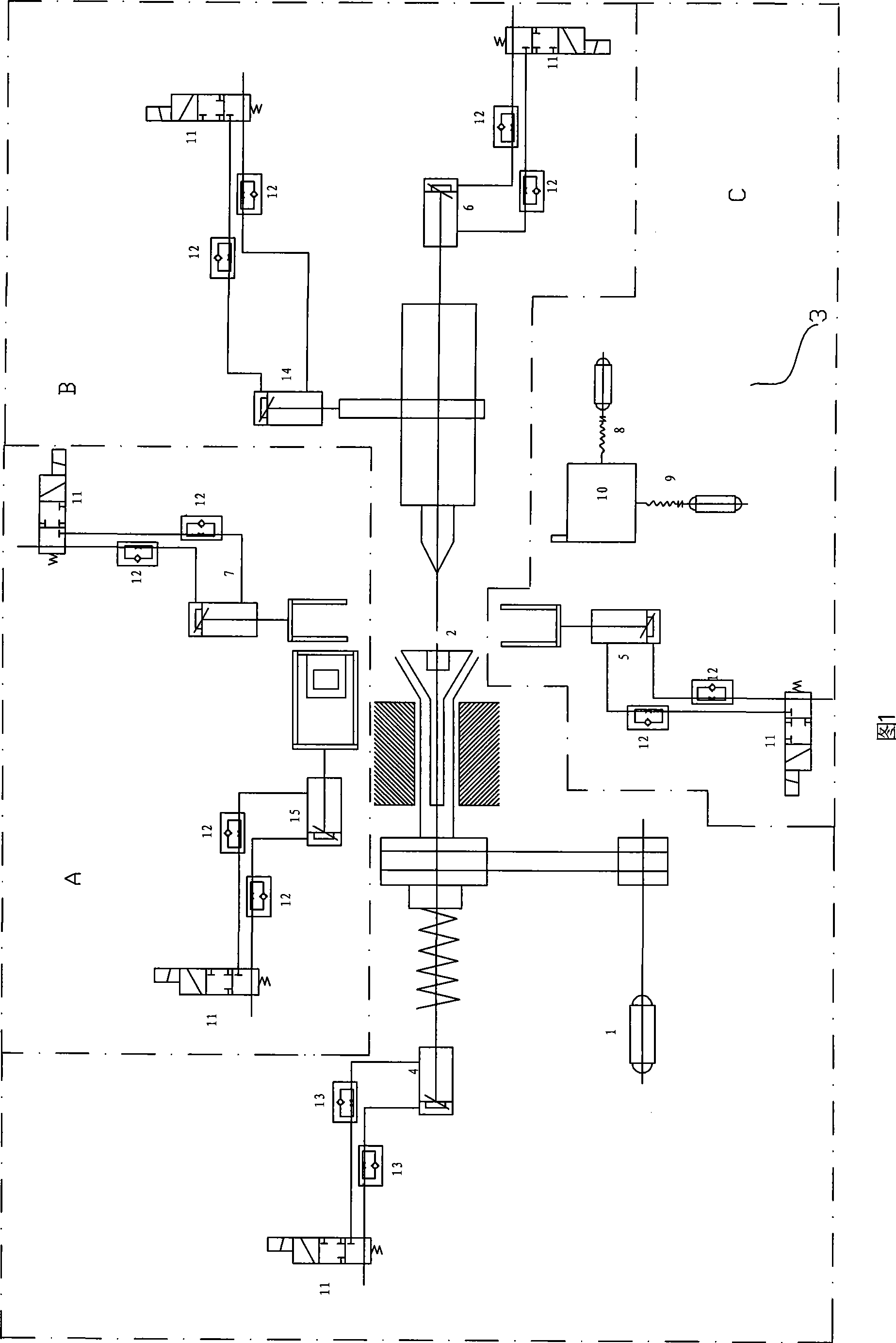
[0039] As shown in the figure, a lathe automatic feeding device for shaft processing, which includes a lathe body, a numerical control system and a control electric box, is similar to the traditional one, and the key point is that a feeding mechanism is installed on the lathe body A. Clamping mechanism B, discharging mechanism C, where:

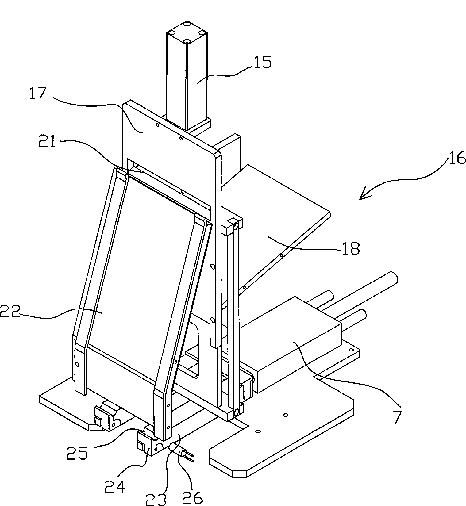
[0040] The feeding mechanism A is installed on the side of the lathe body close to the chuck part 2, so that it is convenient to load the shaft parts to be processed next to it, see Figure 1, 3-5, it includes a feeding rack 16, and the feeding rack 16 is installed There is a feeding cylinder 15, and the feeding cylinder 15 is on the outside of the slide plate 17. The feed rack 15 is obliquely provided with a feed plate 18 on the outside of the slide plate, and an opening for the L-shaped hanging plate 20 to p...


PUM


Abstract

The invention relates to a lathe automatic feeding device used for axial machining, and the structure of the lathe automatic feeding device mainly comprises six parts which are a numerically controlled lathe body, a feeding system, a clamping system, a discharging system, a numerical control system and a control panel. The original lathe needs to be operated by qualified persons and has low efficiency. The improved lathe is mainly characterized in that unmanned automatic processing can be realized, thus not only reducing artificial cost so as to improve the production efficiency and the product quality, but also reducing the risk cost of artificial scrap, and greatly enhancing the product reliability and consistency.

Description

technical field [0001] The invention relates to an automatic feeding device for a lathe. Background technique [0002] In the processing and production of electric motors, it is necessary to widely use CNC lathes to process and produce the shaft branches of electric motors. Since traditional CNC lathes do not have automatic feeding devices, it is very troublesome to use and greatly reduces the processing efficiency of CNC lathes. For example, this CNC lathe During shaft processing, it uses the CNC system to complete automatic tool feed, cutting, tool change and tool retraction. Its main operation process is as follows: [0003] 1. Manually put the shaft branch to be processed into the three-jaw chuck of the lathe; [0004] 2. Lock the three claws with the outer square wrench; [0005] 3. Push the tailstock against the center hole of the iron branch; [0006] 4. Lock the tailstock; [0007] 5. Turn on the switch and start processing; [0008] 6. After the main shaft sto...

Claims


Application Information

Patent Timeline
IPC IPC(8): B23B13/00B23B13/12
Inventor 沈高明
Owner NINGBO XIECHENG POWER TOOLS CO LTD
Why Eureka
Try Eureka