Heat radiation method for LED module

A technology of light-emitting diodes and heat dissipation methods, which is applied to semiconductor devices of light-emitting elements, cooling/heating devices of lighting devices, light sources, etc., and can solve the problems of inability to implement heat pipe technology on a large scale, affect the promotion of LED lights, and fail to meet heat dissipation requirements, etc. To solve the problem, to achieve reasonable design, make up for the lack of heat dissipation, and facilitate the effect of heat dissipation

Inactive Publication Date: 2009-04-29
陈玉新
View PDF0 Cites 7 Cited by
  • Summary
  • Abstract
  • Description
  • Claims
  • Application Information

AI Technical Summary

Problems solved by technology

The main heat dissipation method in China is to connect heat conduction rods on the heat conduction plate in the LED lamp device, and add heat dissipation fins on it. The main disadvantage is that the heat dissipation cannot meet the requirements, which affects the promotion of LED lights.
In addition, the heat pipe technology has been continuously adopted. The disadvantage is that although the heat transfer is improved, the heat pipe technology cannot be implemented on a large scale due to the surrounding mirrors around the heat exchange equipment, and its functions cannot be fully utilized; in addition, the heat pipe pressure is high and there are risks.

Method used


Image

  • Heat radiation method for LED module
  • Heat radiation method for LED module
  • Heat radiation method for LED module

Examples


Embodiment 1

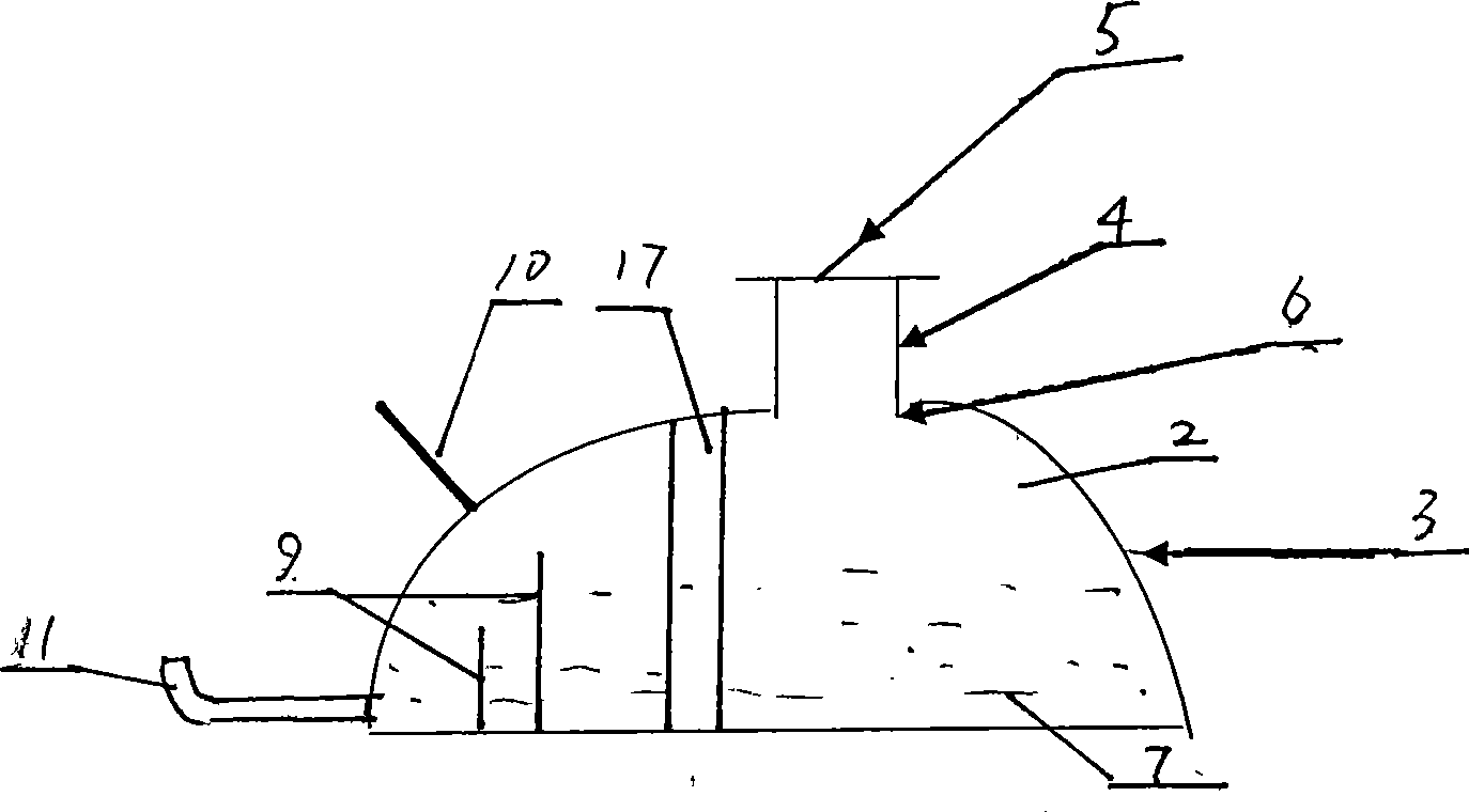
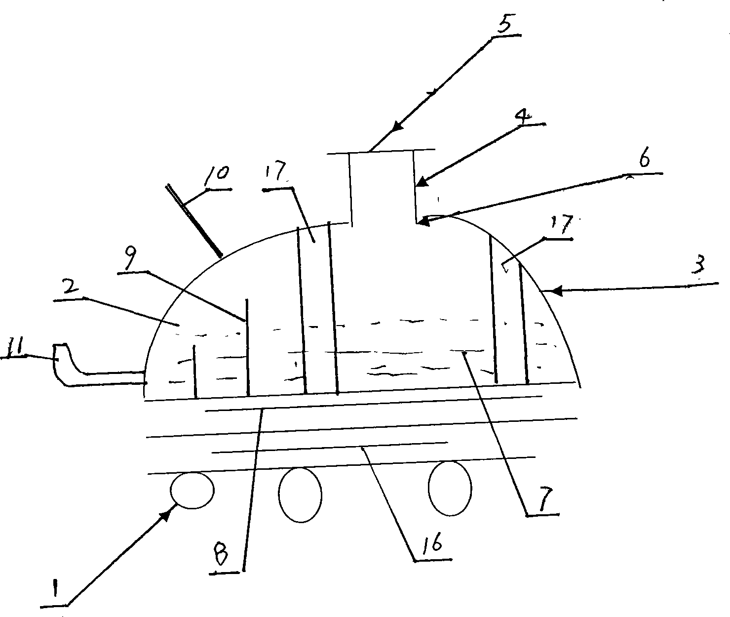
[0022] refer to figure 1 , figure 2 , the present invention includes a main container 3, a short section 4, a cover 5, and the like. The main container 3 is made of heat-conducting materials (such as metal aluminum, aluminum alloy, etc.); and can be made into various shapes. An interface 6 is provided on the outer wall of the main container 3, and the location of the interface 6 is on the top of the container. The short joint 4 communicates with the main container 3 through the interface 6 . The short joint 4 is a columnar hollow structure. A cover 5 is placed on top of the nipple 4 . The cover 5 is elastic, made of stretchable material or metal material, and its area is larger than the cross-sectional area of ​​the interface 6 . After the liquid 7 (water) is poured into the main container 3, the main container 3, the interface 6, the pup joint 4 and the cover 5 form a liquid-filled sealed container in a normal environment. The light-emitting component 1 (heat source) c...

Embodiment 2

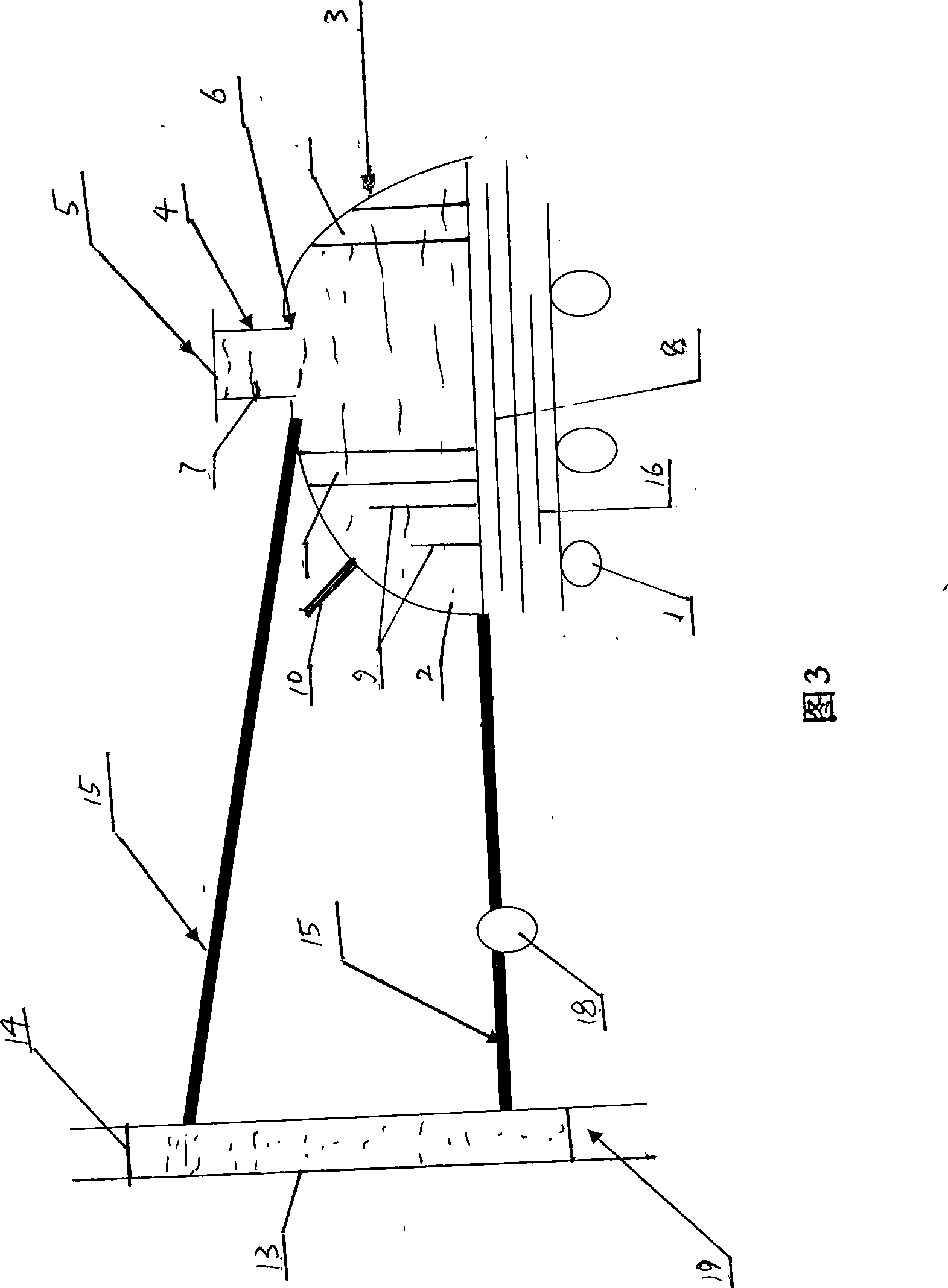
[0024] Referring to Fig. 3, in this embodiment, a secondary liquid-filled sealed container is added. Solve the problem that it is inconvenient to install because a liquid-filled airtight container is too large. The water can also be circulated, communicated with the two interfaces of the auxiliary liquid-filled sealed container through two interfaces and two pipelines, and forms a liquid-filled sealed container system with the main liquid-filled sealed container. The auxiliary liquid sealed container is composed of an auxiliary container main body 13 , an auxiliary container cover 14 and two interfaces connected with the main container 3 . The auxiliary container cover 14 covers the auxiliary container main body 13 . One port of the main container 3 is at the bottom of the side wall of the container, and the other port is at the top of the container, and communicates with the two ports of the secondary container body 13 through two pipelines 15 . At this time, the lid 5 in t...


PUM


Abstract

The invention relates to a radiating method for an LED module, which is characterized in that an LED luminous component contacts the outer wall of a perfusion sealed container closely; the perfusion sealed container consists of a primary tank, a pipe nipple, and a cover, which are encircled by a heat conduction material, wherein the outer wall of the primary tank is provided with a connector, the primary tank is communicated with the pipe nipple through the connector, and the top of the pipe nipple is covered by the cover; and the primary tank is filled with water. Moreover, the method comprises the following steps: A. the amount of heat of the LED luminous component is transmitted into the water in the perfusion sealed container, and is stored by the water; and B. the amount of heat is removed through dissipation of the outer wall of the perfusion sealed container. The method has the advantages that the method has reasonable design, makes the best use of the greater specific heat and heat accumulation function of the water through a water tank for radiating, can fully control the temperature of the LED luminous component in a required temperature range, remedy the dissipation defect of a fin, and prolong the service life of the LED luminous component.

Description

technical field [0001] The invention relates to a heat dissipation method, in particular to a heat dissipation method for a light emitting diode module. Background technique [0002] In recent years, light-emitting diodes (LEDs) have developed rapidly, especially high-power lamps and LED street lamps. There is a problem that has always plagued the industry, that is, light decay and heat dissipation. The main heat dissipation method in China is to connect heat conduction rods on the heat conduction plate in the LED lamp device, and add heat dissipation fins on it. The main disadvantage is that the heat dissipation cannot meet the requirements, which affects the promotion of LED lamps. In addition, the heat pipe technology has been continuously adopted. The disadvantage is that although the heat exchange is improved, the heat pipe technology cannot be implemented on a large scale due to the ring mirror around the heat exchange equipment, and its function cannot be fully utiliz...

Claims


Application Information

Patent Timeline
Patent Type & Authority Applications(China)
IPC IPC(8): F21V29/00H01L23/34F21Y101/02F21V29/56F21Y115/10
Inventor 陈玉新
Owner 陈玉新
Why Eureka
Try Eureka