Cooling apparatus and power converter
A technology for cooling devices and heat exchangers, applied in cooling fluid circulation devices, household refrigeration devices, circuits, etc., can solve the problems of low strength and achieve high strength and good heat release characteristics
Inactive Publication Date: 2010-09-15
MITSUBISHI ELECTRIC CORP
View PDF1 Cites 0 Cited by
- Summary
- Abstract
- Description
- Claims
- Application Information
AI Technical Summary
Problems solved by technology
Method used
View moreImage
Smart ImageViewing Examples
Examples
Embodiment approach 1
Embodiment approach 2
Embodiment approach 3
Login to View More PUM
 Abstract
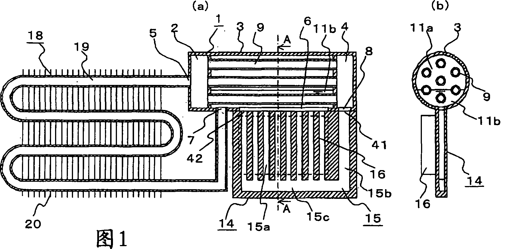
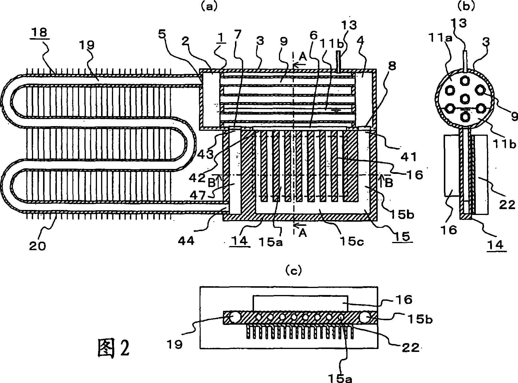
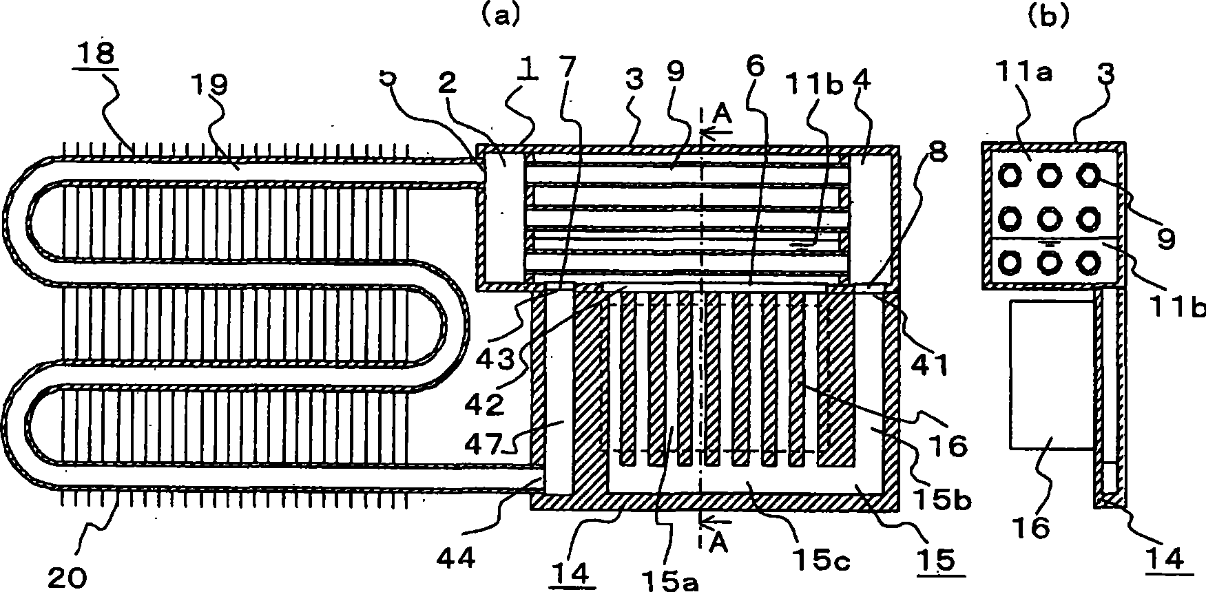
This invention provides a cooling apparatus which has high strength and good heat dissipation. The cooling apparatus comprises a heat exchanger (1). The heat exchanger (1) is joined to an evaporator (14) disposed below the heat exchanger (1) in a face-to-face manner. The heat exchanger (1) in its receiving part (3) has a heat exchanger high-temperature liquid delivery port (7) and has a two-phasefluid intromission port (6) at its joint to the evaporator (14). The heat exchanger (1) in its outlet header (4) has an intermediate liquid delivery port (8) at its joint to the evaporator (14). The evaporator (14) has, at its joint to the heat exchanger (1), a two-phase fluid delivery port (42) opposed to the two-phase fluid intromission port (6) in the receiving part (3) and has, at its joint to the heat exchanger (1), an intermediate liquid intromission port (41) opposed to the intermediate liquid delivery port (8) in the outlet header (3).
Description
Technical field [0001] The present invention involves the heat transmitter, a cooling device that involves the heat of the cooling hair, and the power transformation device using the cooling device. Background technique [0002] In recent years, a large number of electronic instruments have been used in important equipment for energy supply equipment, information and communication equipment, and transportation equipment.These electronic instruments must be able to move stable and reliable, and need to effectively release the heat of electronic instruments.Although there are various ways to heat up, as one of the high -reliability of heat -saving, environmental protection with high reliability, there are cooling devices (for example, referring to patent literature 1).In this cooling device, it is composed of the density difference in circulating solutions generated by the circulating solution of the circulating solution (buoyancy generated by the density difference) in the circula...
Claims
Login to View More Application Information
Patent Timeline
 Patent Type & Authority Patents(China)
IPC IPC(8): F28D15/02F25D9/00F25D17/00H01L23/427
CPCH01L2924/0002H01L23/427F28D15/0266F25B39/02H01L2924/00F28D15/02F25D17/00F25D9/00
Inventor 一法师茂俊高桥哲也东矢和义薮中文春加贺邦彦
Owner MITSUBISHI ELECTRIC CORP
Features
- R&D
- Intellectual Property
- Life Sciences
- Materials
- Tech Scout
- Unparalleled Data Quality
- Higher Quality Content
- 60% Fewer Hallucinations
Learn More Browse by: Latest US Patents, China's latest patents, Technical Efficacy Thesaurus, Application Domain, Technology Topic, Popular Technical Reports.
© 2025 PatSnap. All rights reserved.Legal|Privacy policy|Modern Slavery Act Transparency Statement|Sitemap|About US| Contact US: help@patsnap.com


