Internal bridge connecting and protection implementing method for linkage standby electricity supply mode

A technology of internal bridge wiring and backup power supply, applied in emergency protection circuit devices, electrical components, circuit devices, etc., can solve the problems of increased cost, system complexity, and increased system complexity, and achieves the goal of reducing system cost and simplifying system design. Effect

Active Publication Date: 2009-05-06
NARI TECH CO LTD +1
View PDF0 Cites 19 Cited by
  • Summary
  • Abstract
  • Description
  • Claims
  • Application Information

AI Technical Summary

Problems solved by technology

[0004] When the connection line L3 fails, and the circuit breaker CB3A fails or its corresponding protection 3A fails, the protection 9A can only be used as a failure protection action, and the circuit breaker CB9A trips to remove the fault, causing the fault to spread to the superior station (9A station)
[0005] If the optical fiber is used to transmit the failure remote signal to the protection 9A, the complexity of the system will be increased. If the optical fiber is not used to transmit the failure signal, the protection 9A can only be used as the remote backup of the A station. When the connection line L3 is very long, in order To be able to cut off the fault on the entire tie line L3, the setting range of the protection 9A must be very large, reaching the inside of the transformer T2B, but when there is a heavy load at station A, for example, when a heavy-duty train passes by, the protection 9A may malfunction
[0006] In addition, when the busbar voltage on the high-voltage side of station A is 220KV and above, in order to prevent protection failure, the protection requirements on the high-voltage side busbar are configured in a dual manner, resulting in increased costs and complex systems

Method used


Image

  • Internal bridge connecting and protection implementing method for linkage standby electricity supply mode
  • Internal bridge connecting and protection implementing method for linkage standby electricity supply mode

Examples


Embodiment Construction

[0026] The technical solution of the present invention will be further described in detail below in conjunction with the accompanying drawings of the description.

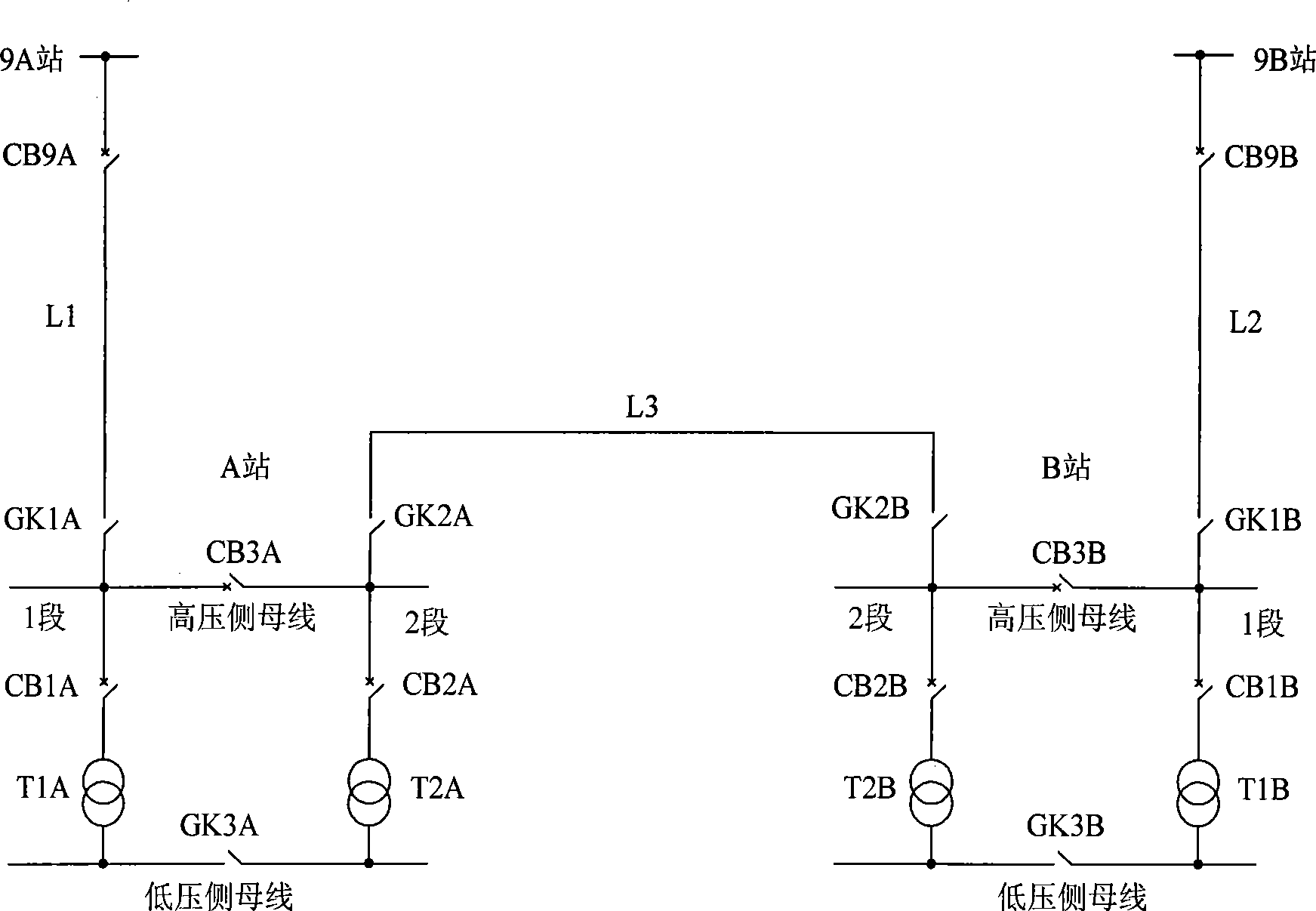
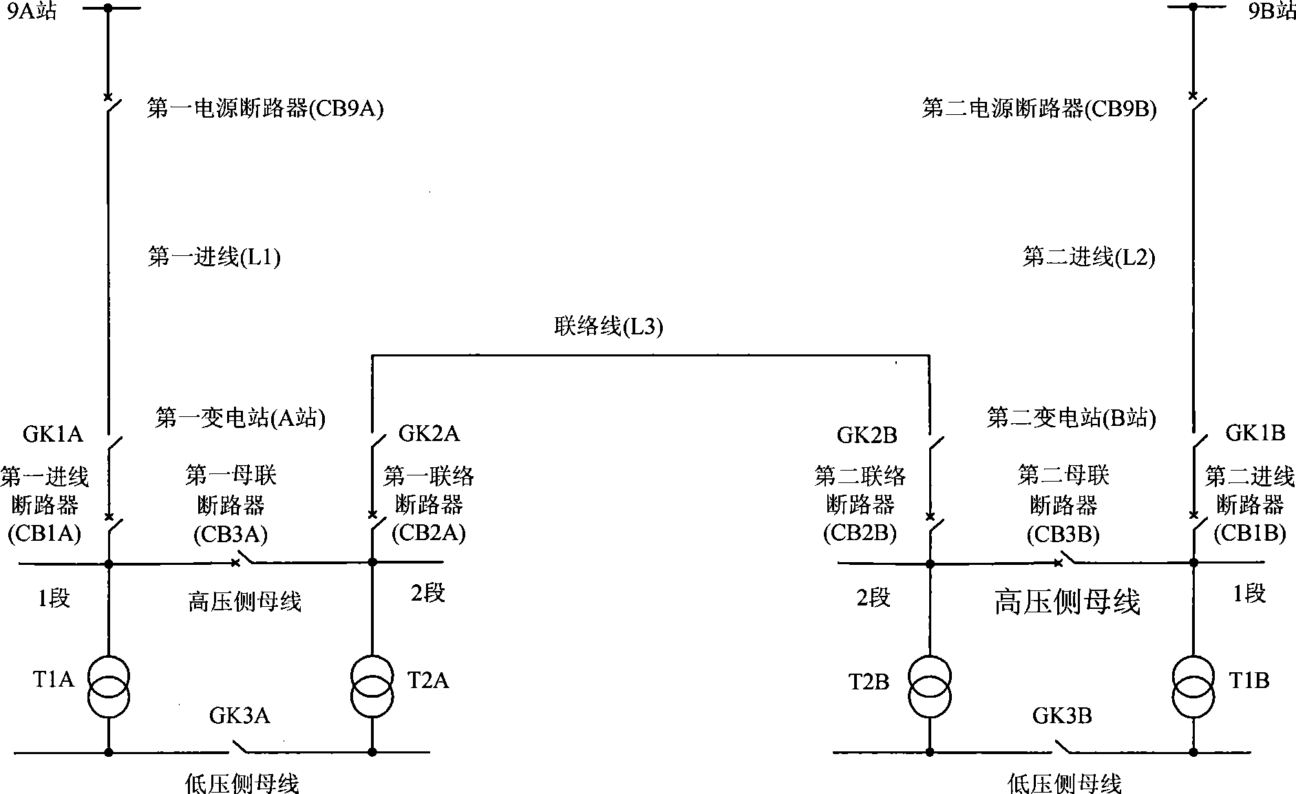
[0027] Such as figure 2 Shown is the wiring diagram of the inner bridge wiring mode of the present invention, the first substation A and the second substation B are two adjacent substations, and the power supply is provided by the first incoming line L1 and the second incoming line L2 respectively, in order to ensure reliable power supply Specifically, the high-voltage side bus bar of the first substation A is connected to the high-voltage side bus bar of the second substation B through a tie line to form a backup power supply mode for linking two substations, which is characterized by:

[0028] Install a first tie circuit breaker CB2A between the tie line and the 2-section bus on the high-voltage side of the first substation A, and install a second tie circuit breaker CB2B between the tie line and the 2-section b...


PUM


Abstract

The stand-by power supply method usually adopts an external bridge wiring way, thereby the problems that the fault is easy to be spread to the upper-layer station and the dual protection is required are caused. In order to solve the problems, the invention provides an internal bridge wiring way, fully utilizes the characteristic that the three circuit breakers of the internal bridge are arranged in a series connection way relative to the incoming line, enables the tripping-position contact of the circuit breaker in front and the tripping contact and the normally closed interlocking contact of a protector in front to be respectively accessed into a protector behind, and achieves the purpose of failure protection of the protection from the protector behind to the protection from the protector in front or the failure protection to the circuit breaker. The number of the circuit breakers and the protectors are not added, the special failure protection device or the special circuit breaker failure protection device is not required to be arranged, and the failure protection or the circuit breaker failure can be protected. When the voltage of the system is 220 kV or more, the protector is not required to be arranged according to the duality, and even if the failure protection occurs, the upper-layer station is not affected when the lower-layer station is out of service. The invention has the advantages that the fabricating cost of the system is reduced, the system design is simplified, and the operation of the transformer is not complex.

Description

technical field [0001] The invention relates to the field of electric technology, in particular to a method applicable to the protection of secondary equipment in a power supply system and the failure protection method of a circuit breaker. Background technique [0002] For important factories and stations, such as railways or factories and mines, in order to ensure reliable power supply, two independent incoming power supplies are usually required, but sometimes the power system cannot provide two independent power supplies. The solution is to connect two adjacent factories and stations , connected through the tie line, so that each factory station only needs one independent power supply. When the incoming line of the factory station fails, the power supply will be provided by the tie line. This power supply method is usually called the link backup power supply method. Such as figure 1 As shown, station A and station B are powered by incoming lines L1 and L2 respectively, ...

Claims


Application Information

Patent Timeline
Patent Type & Authority Applications(China)
IPC IPC(8): H02J3/00H02J9/00H02H7/26
Inventor 李钢刘敬军王灿杨海英
Owner NARI TECH CO LTD
Why Eureka
Try Eureka