
Permanent-magnetic electric motor

A motor, permanent magnet technology, applied in the direction of magnetic circuit rotating parts, magnetic circuit shape/style/structure, manufacturing stator/rotor body, etc., can solve the problem of reduced stator winding electrification, increased copper loss, and inability to fully improve Motor efficiency, etc.

Inactive Publication Date: 2009-05-06
RECHI PRECISION
View PDF0 Cites 8 Cited by
  • Summary
  • Abstract
  • Description
  • Claims
  • Application Information

AI Technical Summary

Problems solved by technology

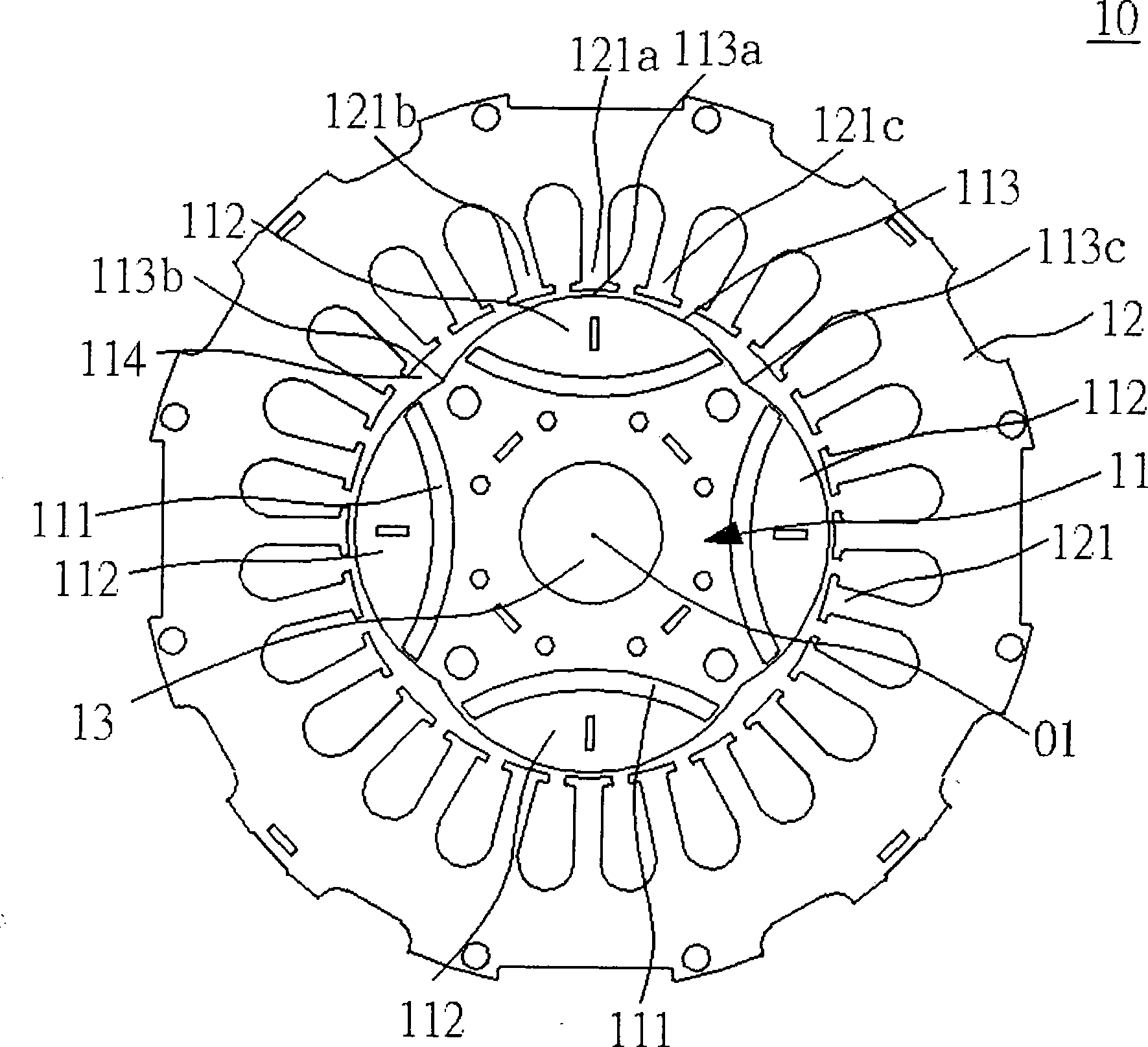
Therefore, the magnetic flux of the stator pole 121a near the center point 113a of the opposite arc surface 113 will concentrate (magnetic flux A), and the magnetism is easy to saturate, while the magnetic flux (magnetic flux B) passing through the stator poles 121b, 121c will decrease, and the stator winding place The electric power induced by induction will be reduced
In this case, in order to increase the electric force induced at the stator winding, the number of turns of the stator winding must be increased, but when the number of turns of the stator winding is increased, the copper loss caused by the stator winding will increase , so the efficiency of the motor cannot be sufficiently improved

Method used


Image

  • Permanent-magnetic electric motor
  • Permanent-magnetic electric motor
  • Permanent-magnetic electric motor

Examples


Embodiment Construction

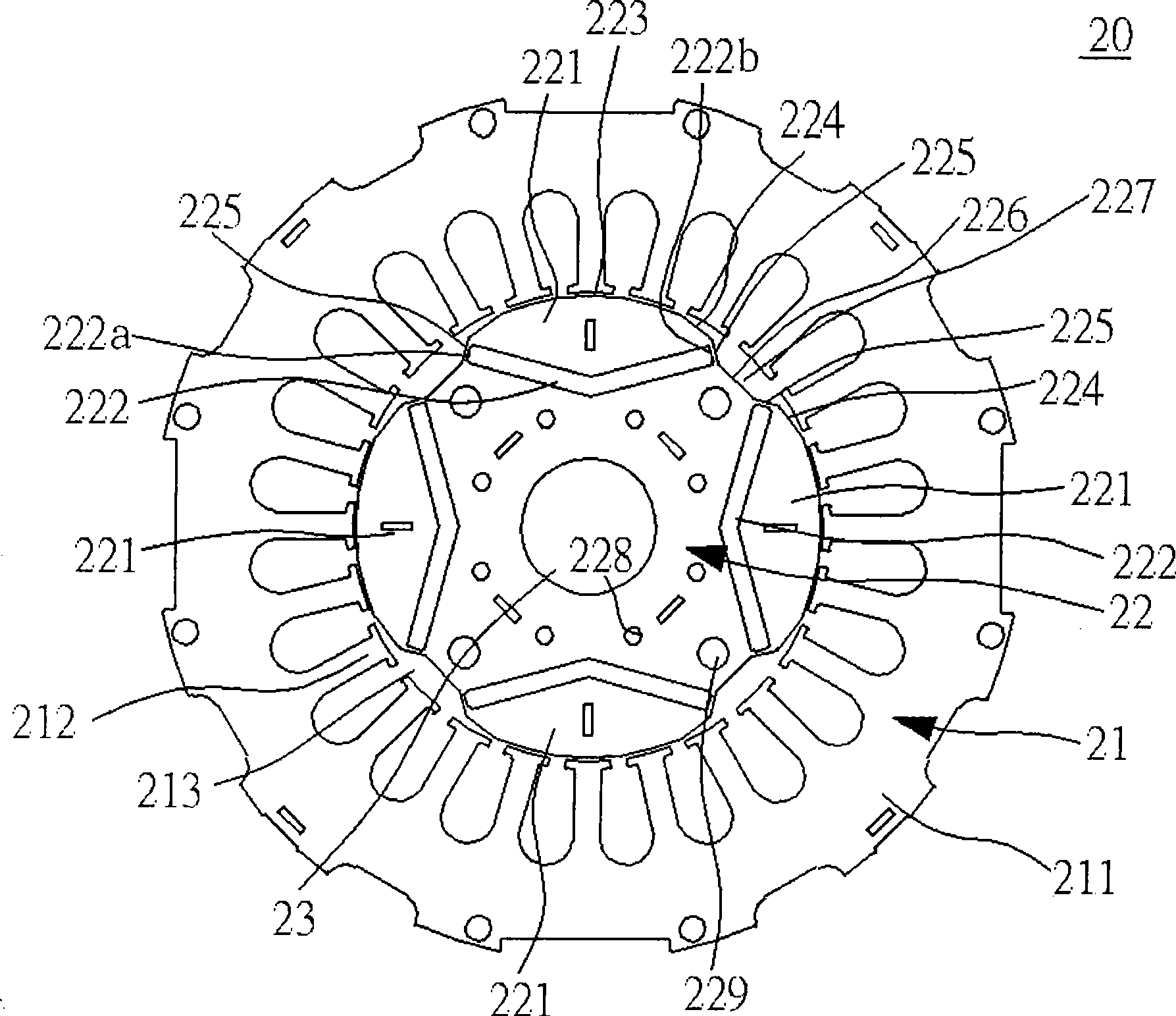
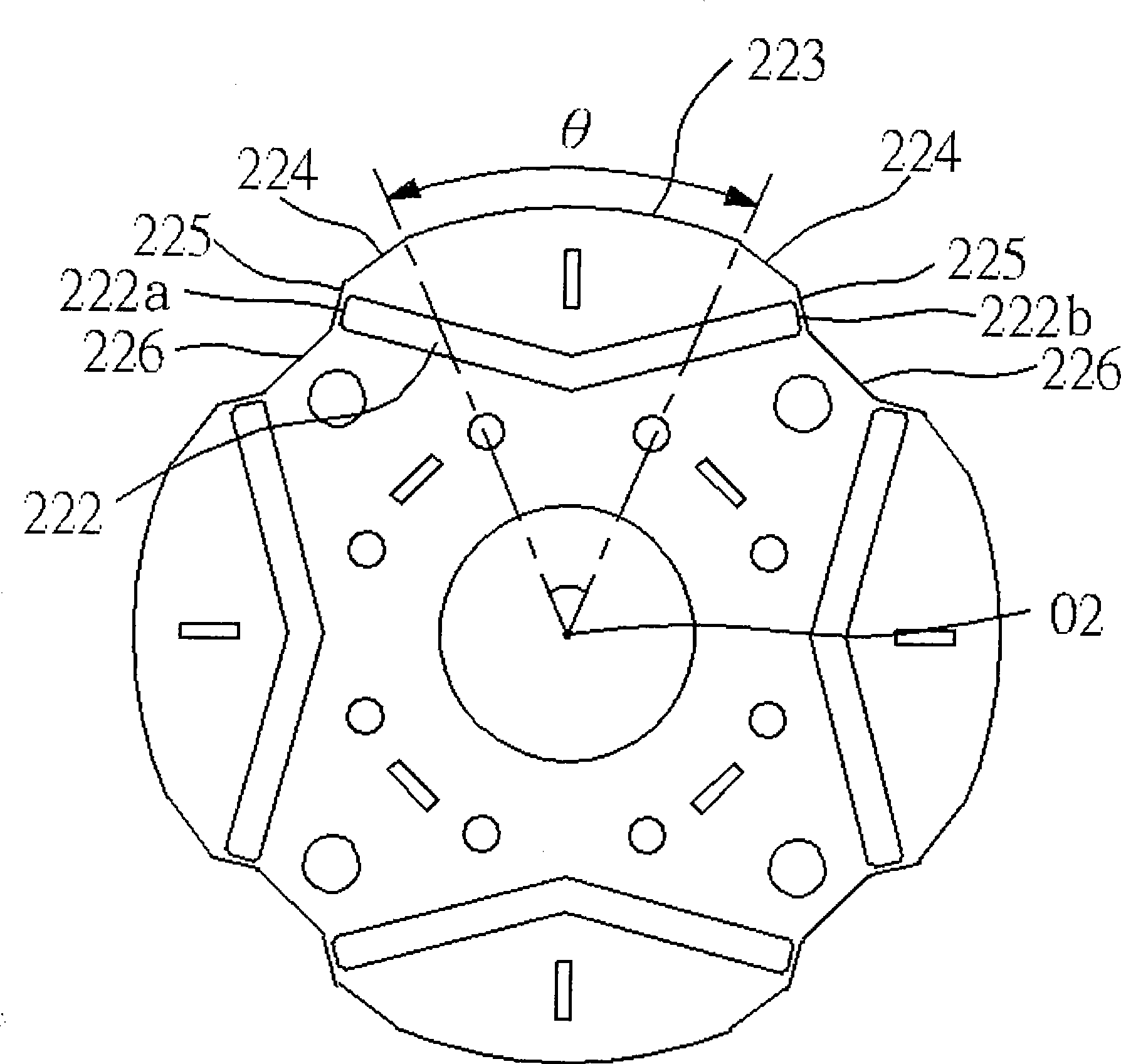
[0030] The present invention mainly improves the rotor in the general permanent magnet motor, such as Figure 2 to Figure 4 As shown, the permanent magnet motor 20 includes: a stator 21, a rotor 22 and a rotating shaft 23; wherein:

[0031] The stator 21 has an annular main body 211 and a plurality of stator poles 212 , each stator pole 212 protrudes inside the main body 211 , and each stator pole 212 forms an accommodating space 213 therein.

[0032] The rotor 22 is a slightly circular piece, is arranged in the accommodating space 213, and has an air gap with each stator pole 212, the rotor 22 is also formed with a plurality of rotor poles 221, and each rotor pole 221 is also provided with There are magnets 222 .

[0033] The number of the plurality of rotor poles 221 is set in an even number, and this implementation takes a four-pole motor as an example, so there are four rotor poles 221, and each rotor pole 221 is provided with an arc surface 223 and two sides of the arc s...


PUM


Abstract

The invention relates to a permanent magnet motor. The permanent magnet motor comprises a stator, a rotor and a rotating axle, wherein the rotor forms a plurality of rotor magnetic poles, each rotor magnetic pole is provided with an arc-shaped surface and first and second inclined sections extending from both sides of the arc-shaped surface, the second inclined sections of the adjacent rotor magnetic poles are connected via a tangent section to form a sunken space, a plurality of magnets are arranged in all the rotor magnetic poles, both end parts of each magnet are arranged adjacent to two second inclined sections, and the center part of each magnet is sunken toward the center of the rotor, so as to fully improve the efficiency of the motor.

Description

technical field [0001] The present invention relates to a permanent magnet motor, and provides a permanent magnet motor that can reduce the change of magnetic flux and reduce the high-order harmonic components contained in the electric power waveform, so as to fully improve the efficiency. Background technique [0002] In today's industry, it is often necessary to provide power to drive the machine to rotate or other forms of motion. At this time, the motor is often used as the power source; because the motor can convert electrical energy or magnetic energy into mechanical energy, it is widely used in various industries and electrical appliances. , transportation systems and other devices, has become an indispensable equipment. [0003] Motors can be roughly divided into DC, AC, brushed, or brushless types. Generally speaking, the structure of a motor is composed of a rotor and a stator. The rotor is driven to rotate by the magnetic flux distribution between the rotor and th...

Claims


Application Information

Patent Timeline
IPC IPC(8): H02K1/27H02K15/03
Inventor 李孝诗余文和
Owner RECHI PRECISION
Learn More