
Control circuit, braking method, energy production method and device for DC motor

A technology of DC motor and control circuit, which is applied in the deceleration device of DC motor, speed/torque control of DC motor, excitation or armature current control, etc. Problems such as reuse and inability to realize the chopper circuit of series-excited DC motor

Inactive Publication Date: 2009-05-06
杨宇强
View PDF6 Cites 31 Cited by
  • Summary
  • Abstract
  • Description
  • Claims
  • Application Information

AI Technical Summary

Problems solved by technology

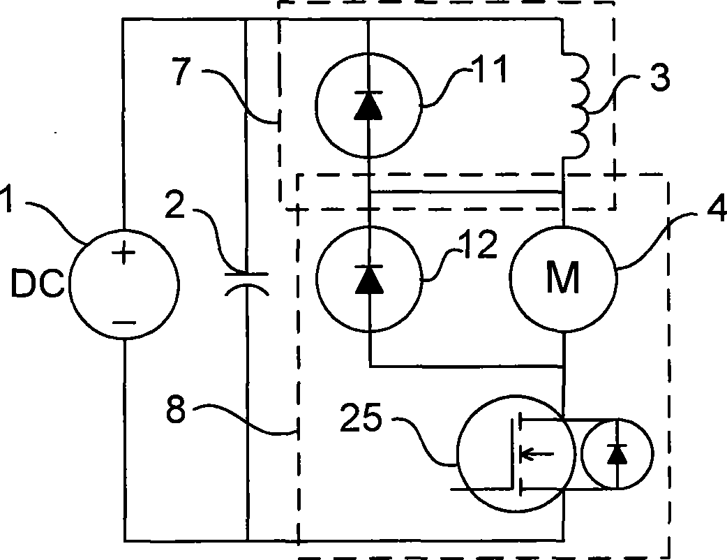
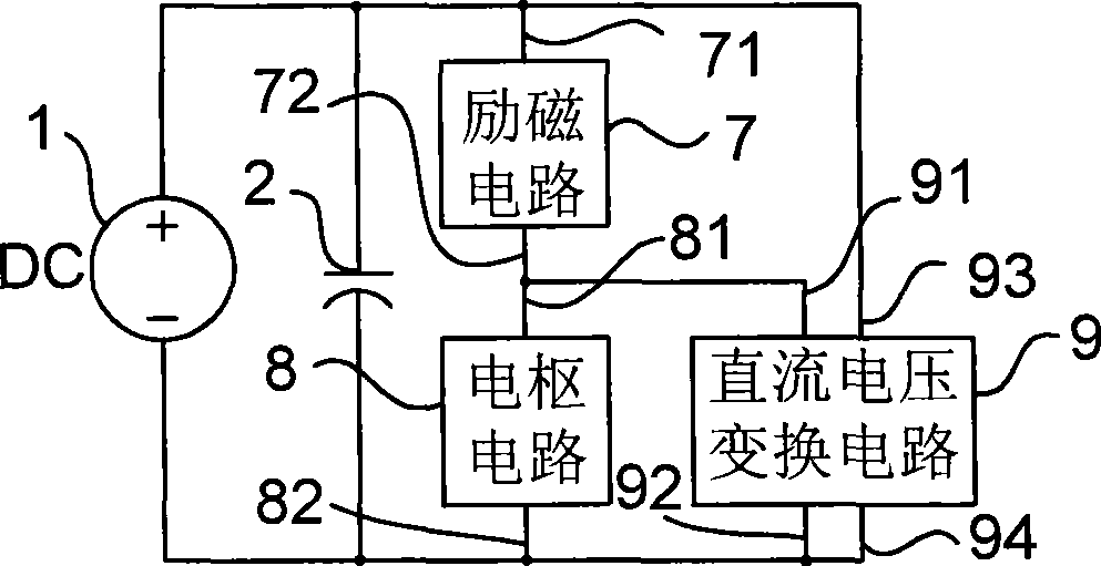
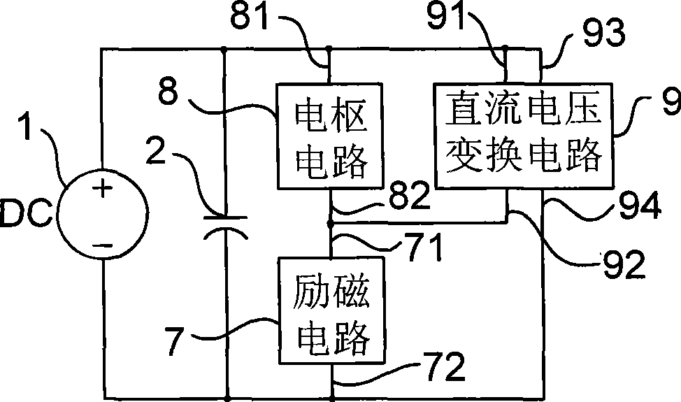
[0012] The present invention aims at the problem in the prior art that the chopper circuit of the series-excited DC motor cannot or cannot realize the feedback or reuse of the braking energy of the series-excited DC motor, and uses a mechanical contact for the reverse control of the existing series-excited DC motor For the problem of contactors, a new circuit scheme was proposed, and a new braking method and power generation method were proposed, as well as a series-excited DC motor drive control device and power generation device made with the new circuit and method

Method used


Image

  • Control circuit, braking method, energy production method and device for DC motor
  • Control circuit, braking method, energy production method and device for DC motor
  • Control circuit, braking method, energy production method and device for DC motor

Examples


Embodiment Construction

[0060] The semiconductor switch in the present invention refers to fully controlled power electronic devices, including power transistors (GTR), field effect transistors (MOSFET), insulated gate bipolar transistors (IGBT), with anti-parallel diodes, if there is no anti-parallel Parallel diodes, anti-parallel diodes should be connected externally in the application. For ease of description, the present invention defines the lead-out terminals of the semiconductor switch as follows: the collector of the power transistor (GTR), the drain of the field effect transistor (MOSFET), the collector of the insulated gate bipolar transistor (IGBT) or other fully controlled The corresponding functional terminal of the power electronic device is defined as 1 pole of the semiconductor switch. The emitter of the power transistor (GTR), the source of the field effect transistor (MOSFET), the emitter of the insulated gate bipolar transistor (IGBT) or the corresponding functional terminal of oth...


PUM


Abstract

The invention relates to a DC motor control circuit, a braking method, an electricity generating method and a device thereof, in particular to the problems of the starting, the speed regulation, the braking and the reversal rotation of a series excitation DC motor. The control circuit comprises an excitation circuit (7), an armature circuit (8) and a DC voltage transforming circuit (9), and has the characteristics of reusing the braking energy and no mechanical contact point in reversal rotating control. The braking method reuses the braking energy, and the electricity generating method utilizes the rotation of the series excitation DC motor to generate electricity. The device of the invention realizes the stable starting, the stepless speed control, the stepless braking and the running of reversal rotation, the energy in braking is fed back or reused, and the energy in braking can be effectively controlled if the series excitation DC motor rotates when the electricity is cut off. No input electric source exists. If the series excitation DC motor continuously rotates under the action of external force, the device is an electricity generator of the series excitation DC motor and can provide an electric source for the outside.

Description

technical field [0001] The patent relates to a motor control circuit, braking method, power generation method and device, especially a control circuit for a series-excited DC motor, its braking method, power generation method and device. Background technique [0002] At present, it is used in traction of urban light rail, trackless and tram, traction of electric locomotives in mines and factories, driving of electric golf carts, electric patrol cars, electric sightseeing cars, electric service vehicles in venues, driving electric forklifts, push trucks, electric motorcycles Series-excited DC motors are widely used in vehicles, bicycles and other lifting and transportation equipment, as well as in other industrial fields that require electric equipment. [0003] In practical applications, the drive control of series-excited DC motors includes starting, speed regulation, braking and reverse. According to the basic knowledge of series-excited DC motors, the methods used to sta...

Claims


Application Information

Patent Timeline
Patent Type & Authority Applications(China)
IPC IPC(8): H02P7/28H02P7/285H02P3/08
Inventor 王创社
Owner 杨宇强
Learn More