Slow opening fast shutting electronic switch circuit and control method thereof

An electronic switch and control method technology, applied in the field of circuits, can solve the problems of long discharge time, long charging time, current-limiting resistance voltage drop loss, reducing inrush current, etc., and reduce the charging time constant and discharging time, output voltage and The effect of low input voltage and improved performance

Active Publication Date: 2009-05-06
WUHAN DRAGONBIO ORTHOPEDIC PROD
View PDF0 Cites 19 Cited by
  • Summary
  • Abstract
  • Description
  • Claims
  • Application Information

AI Technical Summary

Problems solved by technology

[0009] 1. Reducing the capacitance of C12 can only partially reduce the inrush current, and the reduction of the capacitance of C12 is at the expense of weakening the filtering effect and function of the back-end circuit;
[0010] 2. Adding a current-limiting resistor can reduce the inrush current, but during the normal conduction process of the MOS tube, there is a voltage drop and loss on the current-limiting resistor, so that the outpu

Method used


Image

  • Slow opening fast shutting electronic switch circuit and control method thereof
  • Slow opening fast shutting electronic switch circuit and control method thereof
  • Slow opening fast shutting electronic switch circuit and control method thereof

Examples


Embodiment 1

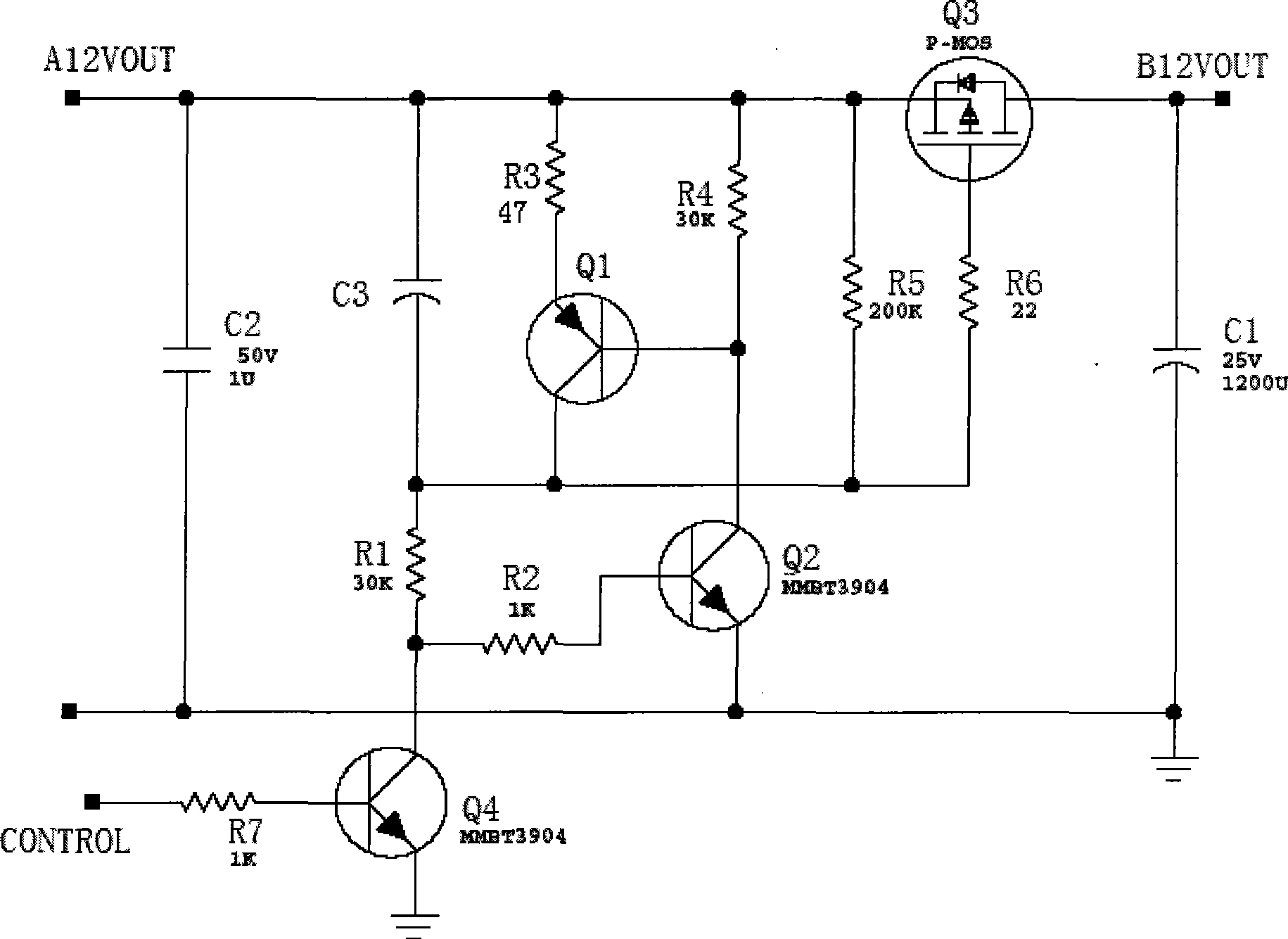
[0032] Such as image 3 As shown, in order to meet the requirements of slow opening and fast closing, the electronic switching circuit of this example adopts the method of adding capacitance between the MOS tubes G and S as the main switching tube, which increases the turn-on time, but due to G, The voltage dividing resistor R5 between S is very large, the discharge resistance of the capacitor is very large when it is turned off, and the RC discharge constant is very large, which will make the turn-off slower than the turn-on, resulting in large loss of the switch tube and easy damage. Therefore, another level of turn-off branch is added. When turning off, the turn-off branch is enabled to discharge the charging capacitor C3 rapidly, the turn-off time is significantly reduced, and the loss of the switch tube is minimized. The turn-off branch includes a discharge resistor R3, a first switch tube Q1, a second switch tube Q2, and the like.

[0033] image 3Among them, the selec...

Embodiment 2

[0037] When the controlled voltage is a negative voltage, such as the controlled voltage in this example is -12V, the electronic switch circuit in this example is as follows Figure 4 As shown, the main switching tube in the above example is replaced by an N-channel MOS tube with a P-channel MOS tube, and the control branch and the turn-off branch are changed accordingly, so that the slow switching and fast switching of the negative voltage can be realized. When the CONTROL signal is at a high level, the transistor Q24 is turned on, and the transistors Q22 and Q21 are turned off. At this time, the charging capacitor C23 is slowly charged through the charging resistor R21, causing Q23 to be turned on slowly. The inrush current on Q23; when the CONTROL signal is low level, Q24 is turned off, Q22 is turned on, causing Q21 to be turned on, C23 is discharged through the discharge resistor R23, and the voltage decreases rapidly, so that Q23 is quickly turned off, which plays a fast r...

Embodiment 3

[0039] This example differs from Example 1 in that, as Figure 5 As shown, when the circuit needs a slower turn-on speed or a faster turn-off speed, it can be achieved by increasing the charging capacitor C3 or reducing the resistance of the charging resistor R3, so that the discharge current of C3 increases. In this case, the first switch tube Q1 can be replaced by a transistor Q31 with a large current-resistant MOS tube Q31 to improve reliability.


PUM


Abstract

The invention discloses an electronic switch circuit of a slow-switch-on and rapid-switch-off type and a control method thereof. The electronic switch circuit comprises a main switch tube, a PC charging and discharging branch circuit, a control branch circuit for receiving control signals, and a switch-off branch circuit, wherein the RC charging and discharging branch circuit is respectively connected with the main switch tube and the control branch circuit. The switch-off branch circuit is connected with a charging capacitor of the RC charging and discharging branch circuit in parallel, and the control end of the switch-off branch circuit is connected with the output end of the control branch circuit. When the control branch circuit outputs a switch-off control signal to the main switch tube, the switch-off branch circuit is conducted, and the charging capacitor of the RC charging and discharging branch circuit is discharged by the switch-off branch circuit. The electronic switch circuit enables the main switch tube to be slow in conduction so as to reduce the impact current and be fast in the switch-off condition to prevent the main switch tube from severely heating to be damaged, thus, the use performance is improved and the service life is prolonged. The electric switch-on and switch-off requirements of different electronic switch circuits can be satisfied by adjusting the charging time constant and the discharging time constant of the RC.

Description

【Technical field】 [0001] The invention relates to a circuit, in particular to an electronic switch circuit. 【Background technique】 [0002] In electronic circuits, a switch circuit is often used to control the output of a voltage. Taking Figure 1 as an example, the MOS tube is used as the main switch tube to realize the output control of B12V. When the control signal CONTROL is high level, B12V outputs. When the control signal CONTROL is low level, B12V has no output. But this kind of circuit has a flaw. When the filter capacitor C12 of B12V has a large value, at the moment when the MOS tube Q12 is turned on, A12V has a very large inrush current, which can reach tens or even hundreds of amperes, resulting in the output power of A12V Overcurrent protection has occurred. [0003] In Figure 1, when the control signal CONTROL is high level, the transistor Q11 is turned on, the P-channel MOS tube is turned on, and B12V is output; when the control signal CONTROL is low level, th...

Claims


Application Information

Patent Timeline
IPC IPC(8): H03K17/08H03K17/60H03K17/687
Inventor 王安山卫延昌陈青昌
Owner WUHAN DRAGONBIO ORTHOPEDIC PROD
Why Eureka
Try Eureka