
Design method for anti-blocking sprayer

A design method and nozzle technology, applied in separation methods, chemical instruments and methods, spray devices, etc., can solve the problems of atomization performance damage, blocking nozzles, and dripping phenomenon, so as to increase atomization performance, increase Large spray angle and long service life

Inactive Publication Date: 2009-05-13
马文龙
View PDF0 Cites 14 Cited by
  • Summary
  • Abstract
  • Description
  • Claims
  • Application Information

AI Technical Summary

Problems solved by technology

The original nozzle gradually forms fouling on the edge of the nozzle, which deteriorates the atomization performance of the nozzle and produces dripping phenomenon, which is not allowed in some occasions. The atomization performance is destroyed during continuous use, and even partially or completely blocked. Hold the nozzle, so as to affect the normal operation of the equipment

Method used


Image

  • Design method for anti-blocking sprayer
  • Design method for anti-blocking sprayer
  • Design method for anti-blocking sprayer

Examples


Embodiment 1

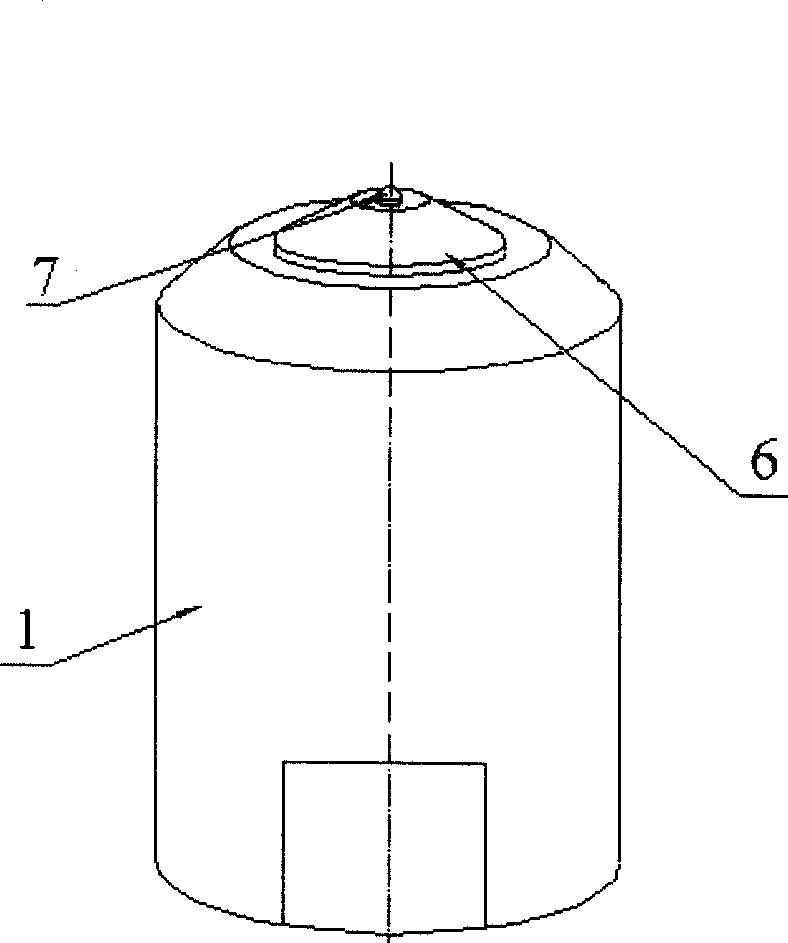
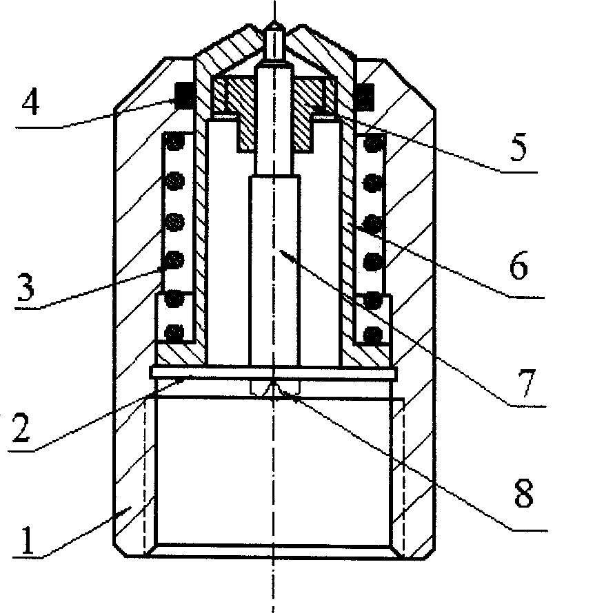
[0016] Example 1 as figure 1 with figure 2 As shown, it is an anti-blocking single-nozzle nozzle. When there is a single nozzle on the top of the center of the housing 1, a spring 3 is sleeved between the piston 10 in the housing 1 and the housing 1, and the bottom end of the spring 3 is placed on the piston. 10, the bottom edge of the piston 10 is placed on the card 2, the cyclone 5 is set on the top of the inner cavity of the piston 10, and the cyclone 5 is sleeved with a single-mouth needle 7, and the single-mouth needle 7 is fixed On the card 2; the bottom end of the housing 1 has a mouthpiece 13 cavity. The top of the single-mouth needle 7 is set on the outlet of the cyclone 5, and the outlet of the cyclone 5 corresponds to the mouth of the nozzle, and the centerline of the single-mouth needle 7 and the centerline of the outlet of the cyclone 5 And the center line of mouth of nozzle of nozzle overlaps mutually in the axial direction, when the top of housing 1 has a noz...

Embodiment 2

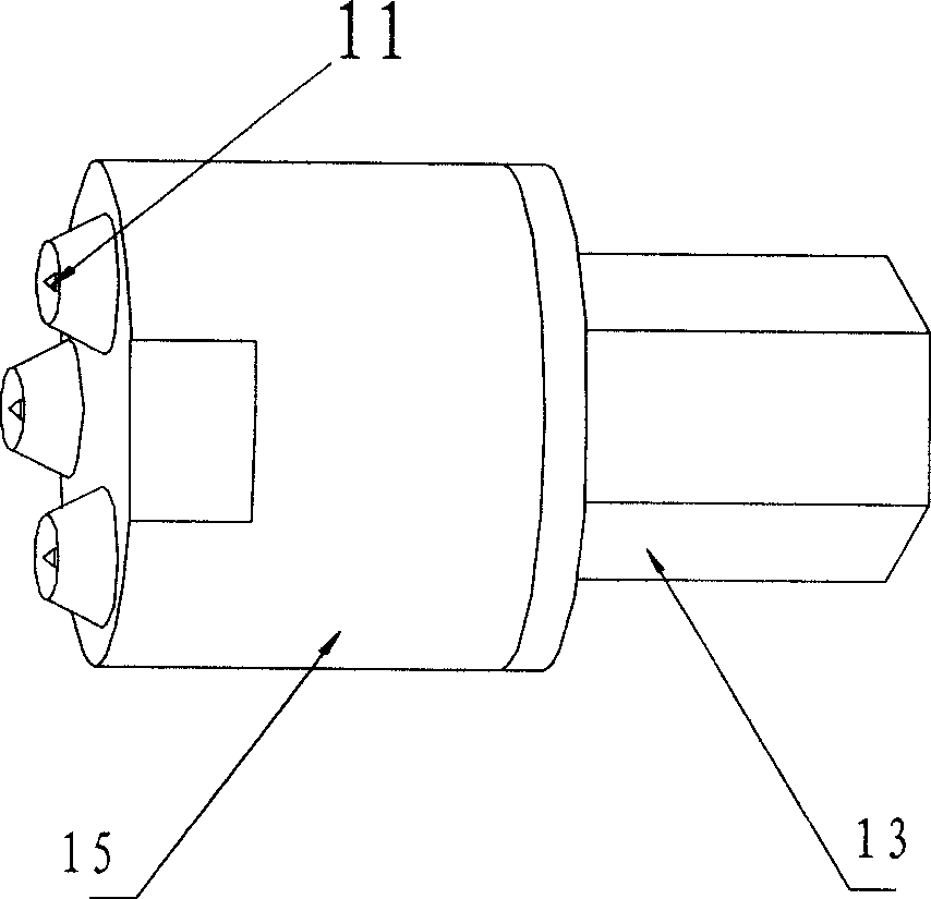
[0018] Embodiment 2 is an anti-blocking multi-nozzle nozzle such as image 3 with Figure 4 As shown, it is an anti-blocking multi-nozzle nozzle. There are multiple nozzles on the top of the multi-mouth housing 15, and a multi-mouth cyclone 16 is set inside each nozzle, and a multi-mouth poking needle 11 is sleeved in each multi-mouth cyclone 16, and the multi-mouth cyclone 16 and the needle 11 are all connected to the top of the piston, the inner cavity of the piston is covered with a spring 14, the bottom of the spring 14 and the lower part of the piston are embedded in the groove at the top of the mouthpiece 13, and the mouthpiece 13 is sealed and connected to the multi-piece by the sealing ring 12. Mouth housing 15 bottoms.

[0019] When installing, first press the multi-nozzle cyclone 16 into the multi-nozzle housing 15, put the piston "O" type seal ring 9 into the piston seal ring groove, and put the nozzle "O" type seal ring 12 into the nozzle 13 in the sealing groov...


PUM


Abstract

The invention relates to a nozzle component in atomizing equipment, in particular to an anti-blocking nozzle used for dust elimination and prevention in situations with a plurality of dust containing relatively complicated dust compositions, such as coal mining, ore mining, cement plants, and power plants. The anti-blocking spraying can be realized by adopting a design method of arranging one or more casings (1) or a multi-nozzle casing (15) at the top of the casing (1). The anti-blocking nozzle automatically clean a spray nozzle when in use, thereby ensuring the smoothness of the spray nozzle and preventing the spray nozzle from being polluted by the external environment; and the anti-blocking nozzle has the advantages of reasonable structure and long service life.

Description

technical field [0001] The present invention is a design method for nozzle components in atomization equipment used in coal mining, mining, dust removal in cement plants, dust removal in power plants, and firefighting, where there is relatively large dust and complex dust components, especially a design for anti-blocking nozzles method. Background technique [0002] Due to the relatively large dust and complex dust components in coal mining, mining, cement plant dust removal, power plant dust removal, and fire protection, the nozzle is installed at the end of the fluid system of water, oil, gas, etc., through water, oil, gas, etc. Work with the pressure fluid provided by the system. The original nozzle gradually forms fouling on the edge of the nozzle, which deteriorates the atomization performance of the nozzle and produces dripping phenomenon, which is not allowed in some occasions. The atomization performance is destroyed during continuous use, and even partially or comp...

Claims


Application Information

Patent Timeline
IPC IPC(8): B05B1/02B05B15/02B01D47/06
Inventor 马文龙
Owner 马文龙
Learn More