Magnetic steel collar

A ring and magnetic technology, applied in textiles and papermaking, can solve the problems of rapid wear, restricting the output and quality of ring spinning, friction and heat generation, etc., and achieve the effects of reducing wear, improving quality and reducing spinning ends.

Inactive Publication Date: 2009-05-13
程心一
View PDF0 Cites 6 Cited by
  • Summary
  • Abstract
  • Description
  • Claims
  • Application Information

AI Technical Summary

Problems solved by technology

When working, the yarn is output from the front roller, passes through the wire ring after passing through the yarn guide hook, and then is wound on the bobbin. Seconds), due to the centrifugal force, the traveler will rub against and heat up and wear out quickly when sliding close to the inner runway of the steel ring at high speed, thus restricting the output and quality of ring spinning

Method used


Image

  • Magnetic steel collar

Examples


Embodiment Construction

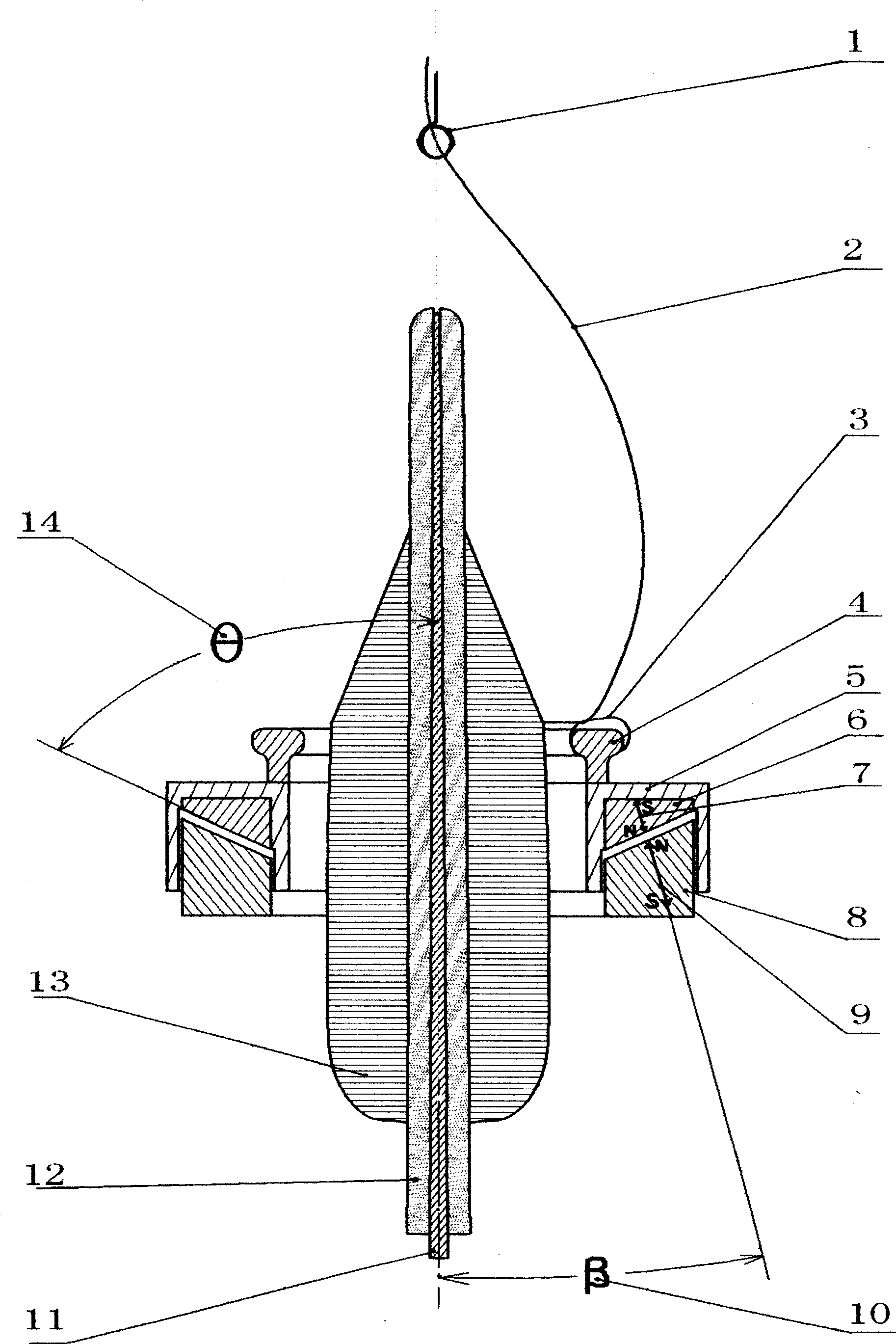
[0010] In the figure, the magnetic levitation layer (6) is installed above the magnetic base (8) and coaxial with the magnetic base (8). Because the magnetic pole direction (7) of the magnetic levitation layer is opposite to the magnetic pole direction (9) of the magnetic base, from the axial section of the spindle (11) axis, the opposite surface of the magnetic levitation layer (6) and the magnetic base (8) is opposite to the spindle There is an included angle (14) between the axes. Therefore, the magnetic suspension layer (6) is suspended above the magnetic base (8), the magnetic isolation layer (5) is fixedly installed on the magnetic suspension layer (6), the circular track (4) is fixedly installed on the magnetic isolation layer (5), and the steel wire Circle (3) is looped on the annular track (4). When working, the yarn (2) is output from the front jaw, passes through the traveler (3) after passing through the yarn guide hook (1), and then is wound on the bobbin (12) to...


PUM


Abstract

The invention provides a magnetic ring used for spinning machinery. The lower part of the magnetic ring is provided with a magnetic base; a magnetic suspension layer is arranged above the magnetic base; the magnetic base and the magnetic suspension layer are provided with the same axes; as the magnetic polarity of the magnetic suspension layer is opposite to that of the magnetic base, the magnetic suspension layer suspends above the magnetic base; a magnetism isolating layer and an annular track are fixed on the magnetic suspension layer; and a wire loop is movably sleeved on the annular track. When the magnetic ring works, a yarn is outputted form a front jaw, passes through the wire loop after passing a twizzle, and is wound on a yarn cop. When the wire loop slides on the annular track, rubbing action can drive the annular track and the magnetic suspension layer to equidirectionally rotate, so that high-speed frictional sliding between the prior ring and wire loop is decomposed into two relative low-speed motions between the magnetic base and the magnetic suspension layer, and between the annular track and the wire loop. Therefore, friction of the wire loop and the annular track is greatly reduced, and further improvement for vehicle speed in the future becomes possible.

Description

technical field [0001] The invention relates to a spinning device. Background technique [0002] The steel collar of existing ring spinning frame and twisting frame is the key component on the spinning frame, and it cooperates with parts such as steel traveler, spindle, bobbin to jointly complete the twisting and winding of yarn. The existing steel ring is in the shape of a ring. The lower part of the steel ring is a ring-shaped base, and the upper part has a circular track. The steel wire loop is set on the circular track of the steel ring. Sliding, the upper and lower parts of the steel ring are machined from a single piece of metal material. When working, the yarn is output from the front roller, passes through the wire ring after passing through the yarn guide hook, and then is wound on the bobbin. Seconds or so), due to the centrifugal force, the traveler will rub against and heat up and wear out quickly when it slides close to the inner track of the steel ring at hig...

Claims


Application Information

Patent Timeline
Patent Type & Authority Applications(China)
IPC IPC(8): D01H7/60
Inventor 程心一
Owner 程心一
Why Eureka
Try Eureka