
Motorized lift device

A lifting device, electric technology, applied in the direction of lifting devices, cabinets, buildings, etc., can solve the problems of large working noise, failure, and difficulty in installing low-profile TVs, etc., to achieve the effect of eliminating intermittent collisions

Inactive Publication Date: 2009-05-13
维斯劳·鲍勃尔
View PDF12 Cites 13 Cited by
  • Summary
  • Abstract
  • Description
  • Claims
  • Application Information

AI Technical Summary

Problems solved by technology

The lift mechanism is designed to be difficult to mount a low-profile TV on and can be dangerous if fingers get caught in the platform
If there is a slight misalignment of the lifting device, it will cause a lot of working noise or malfunction

Method used


Image

  • Motorized lift device
  • Motorized lift device
  • Motorized lift device

Examples


Embodiment Construction

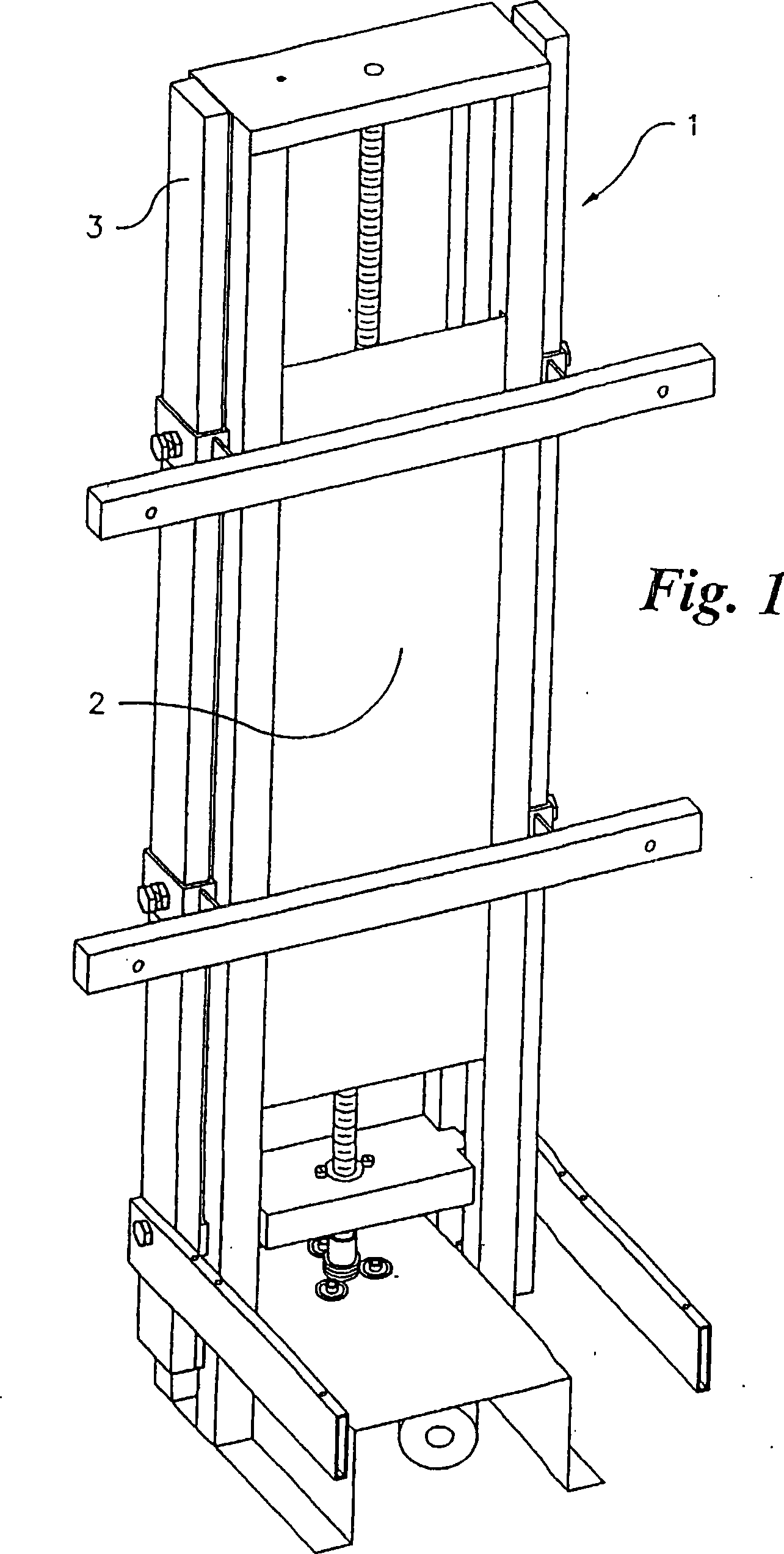
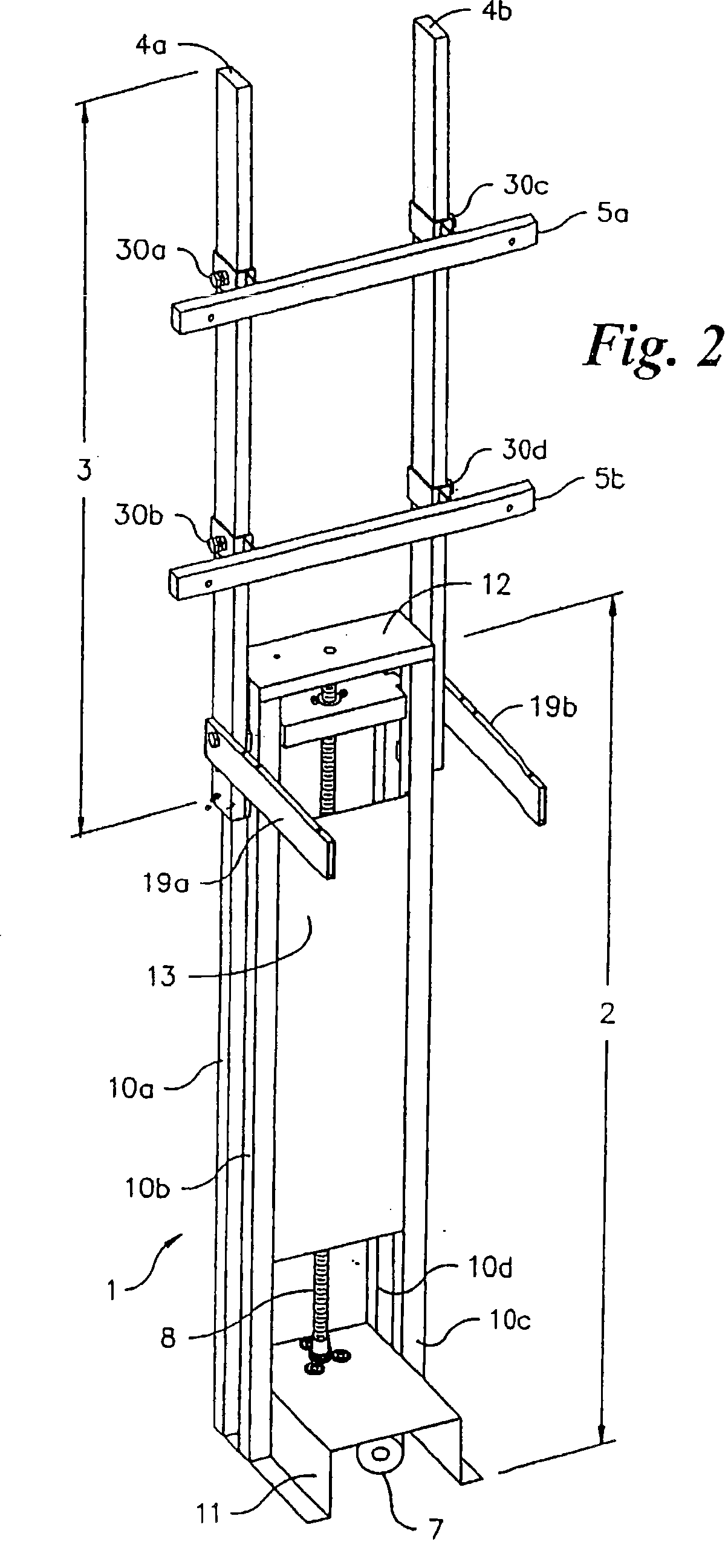
[0063] Referring to FIG. 1 , which is an exemplary embodiment of the present invention, the figure shows a retracted state of a lift 1 for vertically placing a low-profile display, and is characterized in that a supporting device 3 surrounds a base device 2 . FIG. 2 shows the lift 1 with the supporting device 3 protruding from the base device 2 .

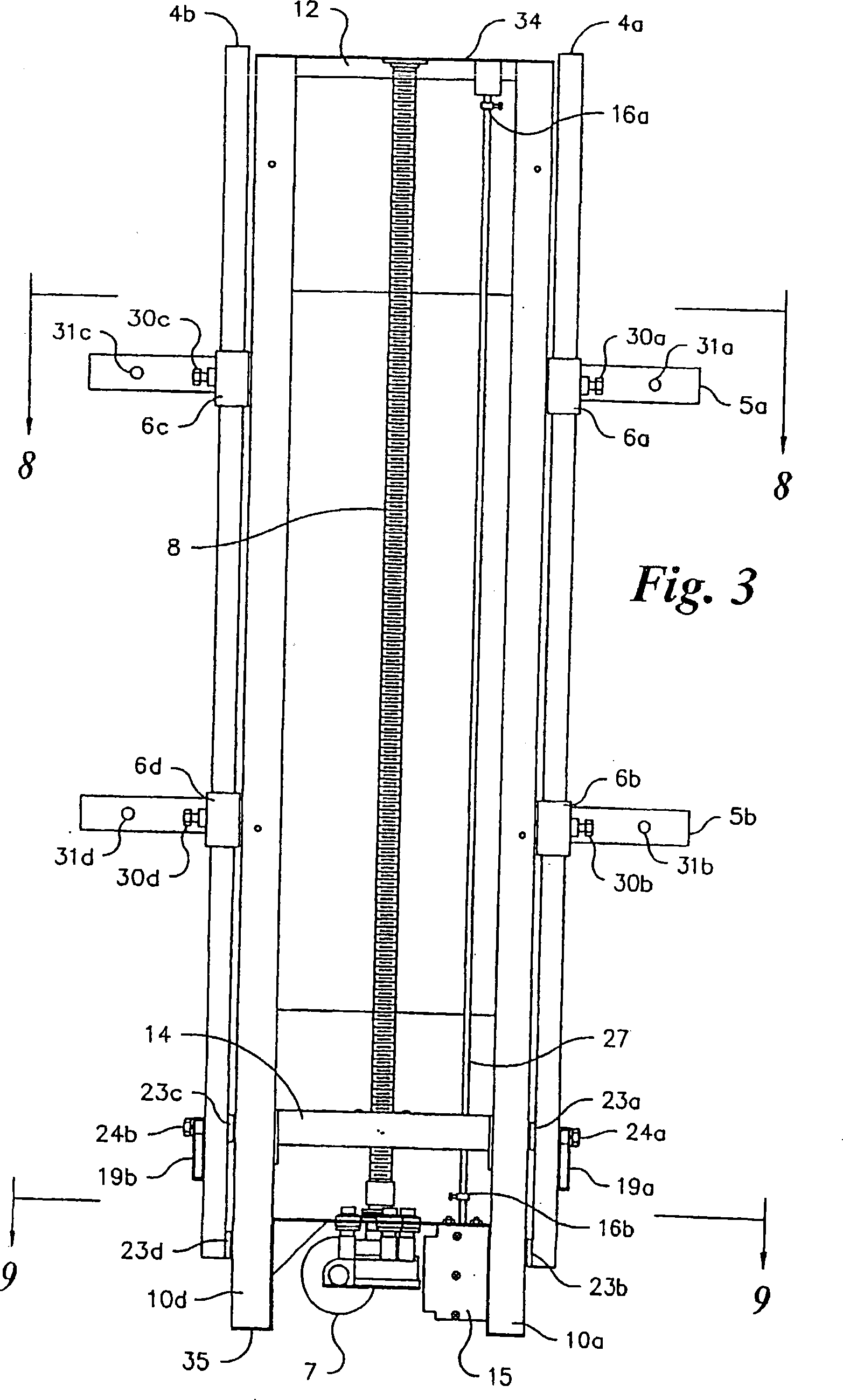
[0064] Referring again to FIG. 2 , the base device 2 includes a base 11 , four rails 10 a - 10 d , an end plate 12 and a reinforcement 13 . The base 11 is a U-shaped component made of sheet metal, preferably steel. The rails 10a-10d can be solid or hollow in structure, and preferably have a square or rectangular cross-section. The rails 10a-10d are arranged in pairs, 10a-10b and 10c-10d are located on both sides of the U-shaped base 11, such that one end of each rail 10a-10d contacts the base 11 adjacent the lower end 35, as shown in FIG. The rails 10a-10d are welded or fixed to the base 11 by known techniques so as to be arranged...


PUM


Abstract

A motorized lift device facilitating the uninterrupted and nearly noiseless movement of a low-profile television. The motorized lift comprises a base unit having a support unit slidably disposed thereon in a vertically-oriented and telescoping fashion. Support unit movement is controlled via a motor directly coupled to a transmission which is coupled to a screw. Coupling between screw and an elevator plate converts screw rotation to linear motion within the support unit. A low-friction floating nut between elevator plate and screw, as well as several low-friction couplings between base unit and support unit reduce noise, wobbling, eliminate binding, and accommodates for misalignments during movement. The support unit accommodates for vertical and horizontal adjustability during mounting and installation of any size low-profile television.

Description

[0001] Cross References to Related Applications [0002] This PCT patent application claims priority to US Patent Application Serial No.: 10 / 916,953 filed on August 12, 2004 and abandoned on the same date; US Patent Application filed on August 12, 2004 is February 10, 2003 A continuation-in-part of filed US Patent Application Serial No. 10 / 361,421. technical field [0003] Generally, the present invention relates to an electric lift. In particular, the present invention relates to a vertically positioned lifter that facilitates undisturbed, almost noiseless movement of plasma screens and other low profile televisions. Background technique [0004] The trend in television design is to focus on low-profile devices, including but not limited to plasma displays and liquid crystal displays (LCDs). Low-profile TVs maximize display area while minimizing device thickness. However, all designs were inevitably poorly decorated, unstable, and heavy compared with CRT televisions. ...

Claims


Application Information

Patent Timeline
Patent Type & Authority Applications(China)
IPC IPC(8): A47B9/00E02F3/00B66F9/00B66C23/00B66F9/02
CPCA47B81/06B66F9/02A47B9/00B66C23/00B66F9/00
Inventor 韦斯利·鲍勃尔
Owner 维斯劳·鲍勃尔
Learn More