Riveting method

A technology of riveting and riveting points, which is applied in the field of mechanical processing, can solve the problems of poor appearance of riveting parts, complicated process, poor reliability, etc., and achieve the effects of reducing energy consumption, reducing manufacturing costs and high production efficiency

Inactive Publication Date: 2009-05-20
李殷德
View PDF0 Cites 13 Cited by
  • Summary
  • Abstract
  • Description
  • Claims
  • Application Information

AI Technical Summary

Problems solved by technology

The existing traditional technology adopts spot welding or straight riveting, which not only has complicated process and

Method used


Image

  • Riveting method
  • Riveting method
  • Riveting method

Examples


Example Embodiment

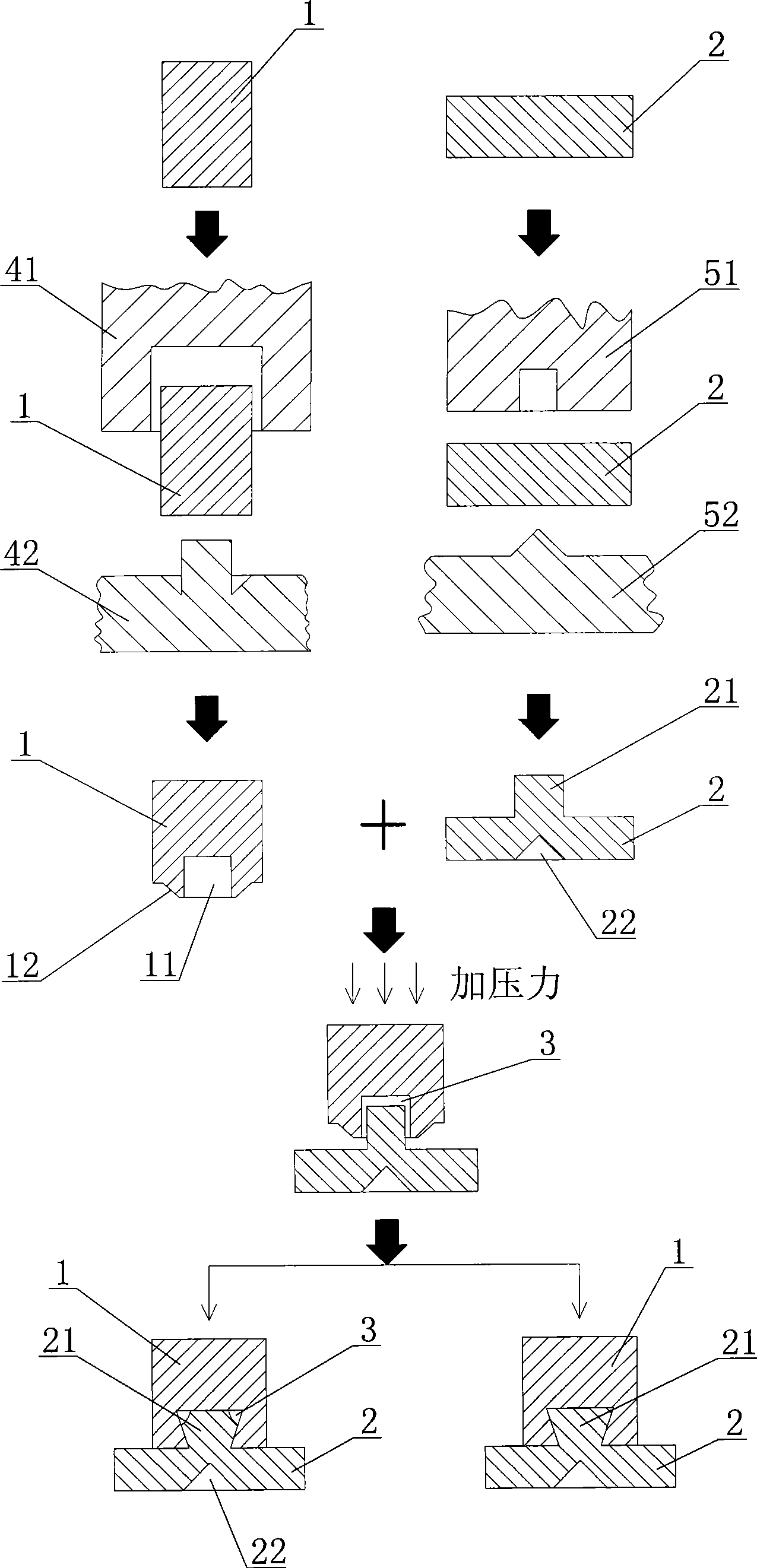
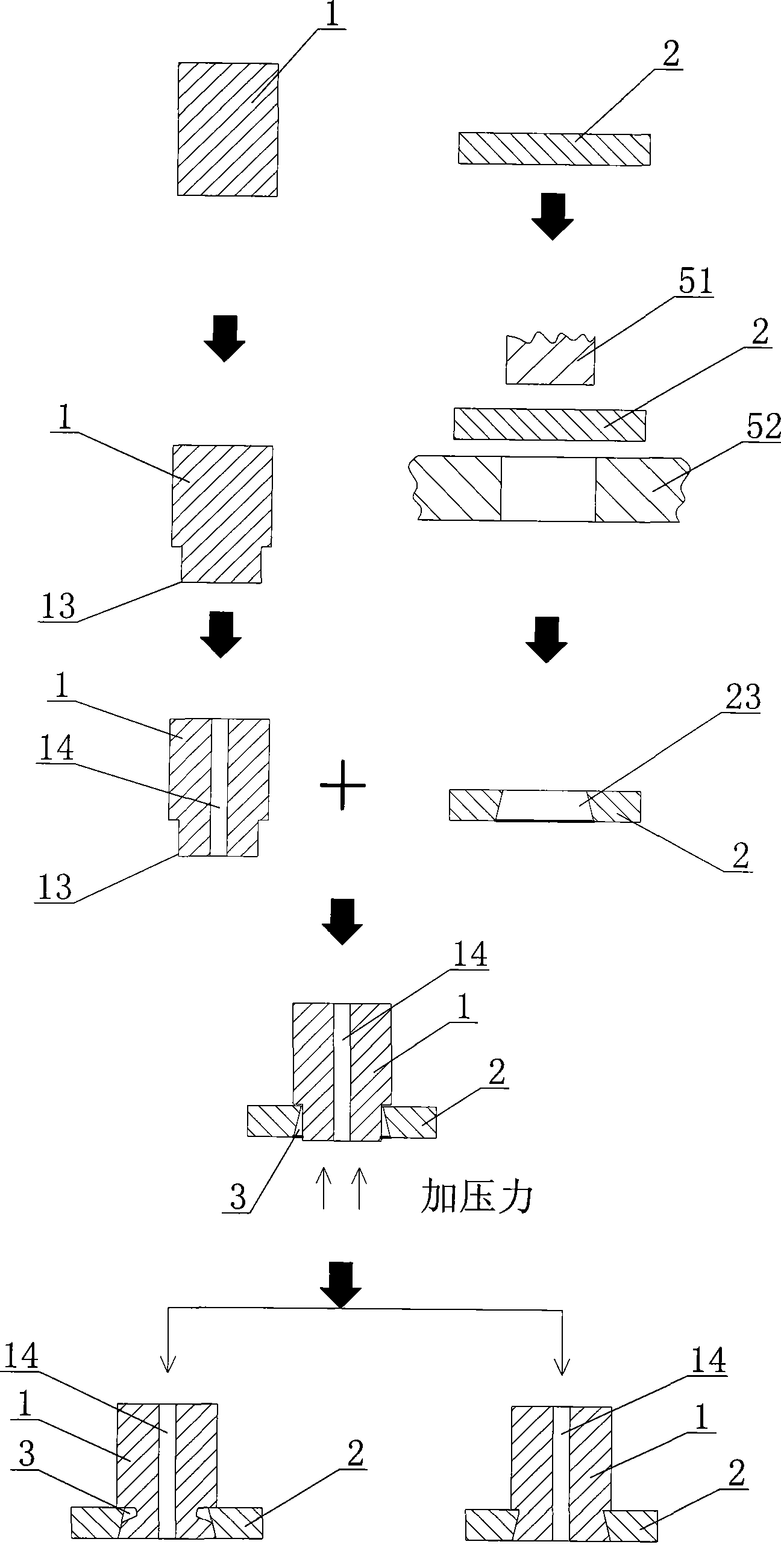
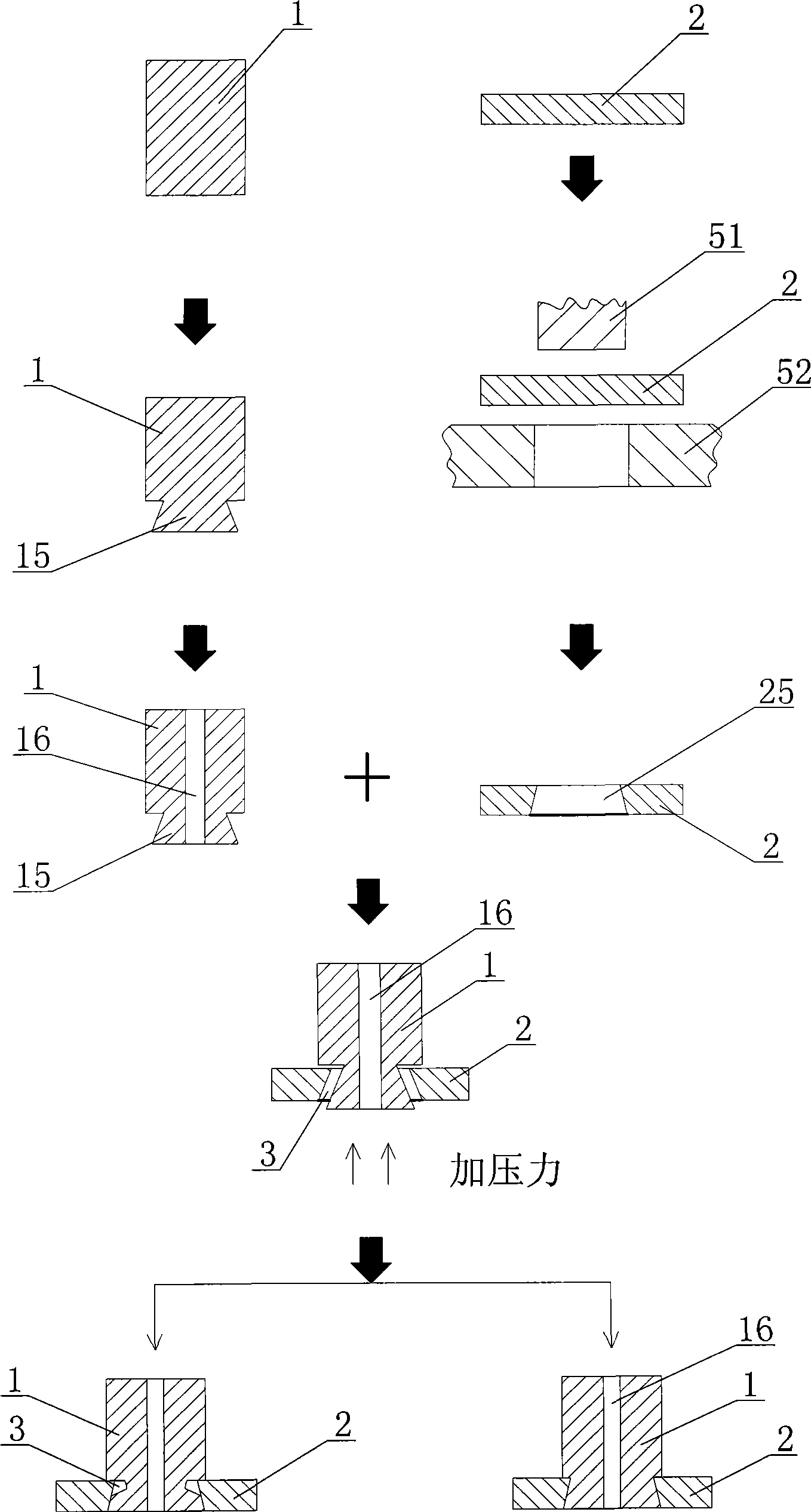
[0014] Such as Figure 1 ~ Figure 4 As shown, the riveting method of the present invention includes the following steps: first use the traditional machining method of stamping or lathe processing to preprocess the two metal elements to be riveted, and form a gap 3 at the riveting point of the two metal elements to be riveted, and then Pressure is applied at the riveting points of the two metal elements to be riveted by combined punching riveting, so that the two metal elements squeeze each other and fill the gap 3 to form a firm connection. Among them, according to the pretreatment of the shape and characteristics of the metal components to be riveted and the appearance performance requirements after combined punching and riveting, the present invention includes but not limited to the following four embodiments, such as figure 1 As shown, the above-mentioned riveting method may include the following steps: first, at the riveting point at the bottom of the metal cylinder 1 to be ri...


PUM


Abstract

The invention relates to a riveting method, which comprises the following steps: firstly, two metal elements to be riveted are pretreated by utilizing the prior machining method of punching or lathe processing, and a gap is formed on a riveted point of the two metal elements to be riveted; and secondly, pressure is applied on the riveted point of the two metal elements to be riveted through combined punched riveting, so that the two metal elements mutually extrude and fill up the gap to form firm connection. The riveting method adopts the two-step method of combining pretreatment by the prior machining method and filling of hollow cavities and expanded angles, and performs the pretreatment of certain shape on the metal elements to be mutually riveted by utilizing the prior machining method of punching or lathe processing first; after the riveted point is formed, the combined punched riveting is used to make the two metal elements provided with the hollow cavities before combination mutually extrude influenced by punching and fill up the hollow cavities to form a reversely suspended locking mechanism which is partially filled or fully filled, so the aim of firm riveting is achieved.

Description

technical field [0001] The invention belongs to the technical field of mechanical processing, and in particular relates to a riveting method between metal elements with a certain shape. Background technique [0002] For the permanent riveting process of metal, which needs to meet the requirements of appearance and reliability at the same time, it has always been very difficult. The existing traditional process uses spot welding or straight riveting, which not only has a complicated process and low production efficiency, but also has poor firmness and poor appearance of the riveted part after electroplating. Contents of the invention [0003] The purpose of the present invention is to address the deficiencies of the prior art, to provide a riveting that is firm and reliable in connection, high in production efficiency, can effectively reduce energy consumption and save materials, and is especially suitable for the cavity expansion angle of the speaker rear splint in the ele...

Claims


Application Information

Patent Timeline
IPC IPC(8): B21D39/00B21D37/10B23P13/00
Inventor 李殷德
Owner 李殷德
Why Eureka
Try Eureka