Universal joint

A power transmission and sliding shaft technology, applied in the field of universal joints, can solve problems such as increased clearance, reduce assembly clearance and noise, and improve strength and rigidity

Active Publication Date: 2009-05-20
HL MANDO CORP +1
View PDF0 Cites 3 Cited by
  • Summary
  • Abstract
  • Description
  • Claims
  • Application Information

AI Technical Summary

Problems solved by technology

Therefore, as the solid portion 150 is worn, the gap between the solid portion 150 and the shaft tube 110 increases, thereby generating unexpected noise

Method used


Image

  • Universal joint
  • Universal joint
  • Universal joint

Examples


Embodiment Construction

[0029] A series of embodiments of the present invention and their corresponding drawings will be cited below for illustration. In the following description and drawings, the same reference numerals are used to represent the same or similar units, so the description of the same or similar units will not be repeated. Furthermore, detailed descriptions of known functions or structures are not repeated here to avoid obscuring the main subject of the present invention.

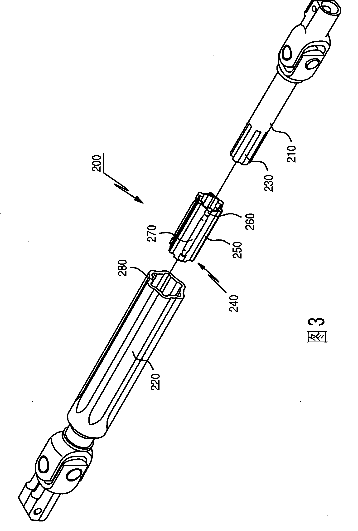
[0030] Fig. 3 is an exploded perspective view showing a universal joint according to a first embodiment of the present invention.

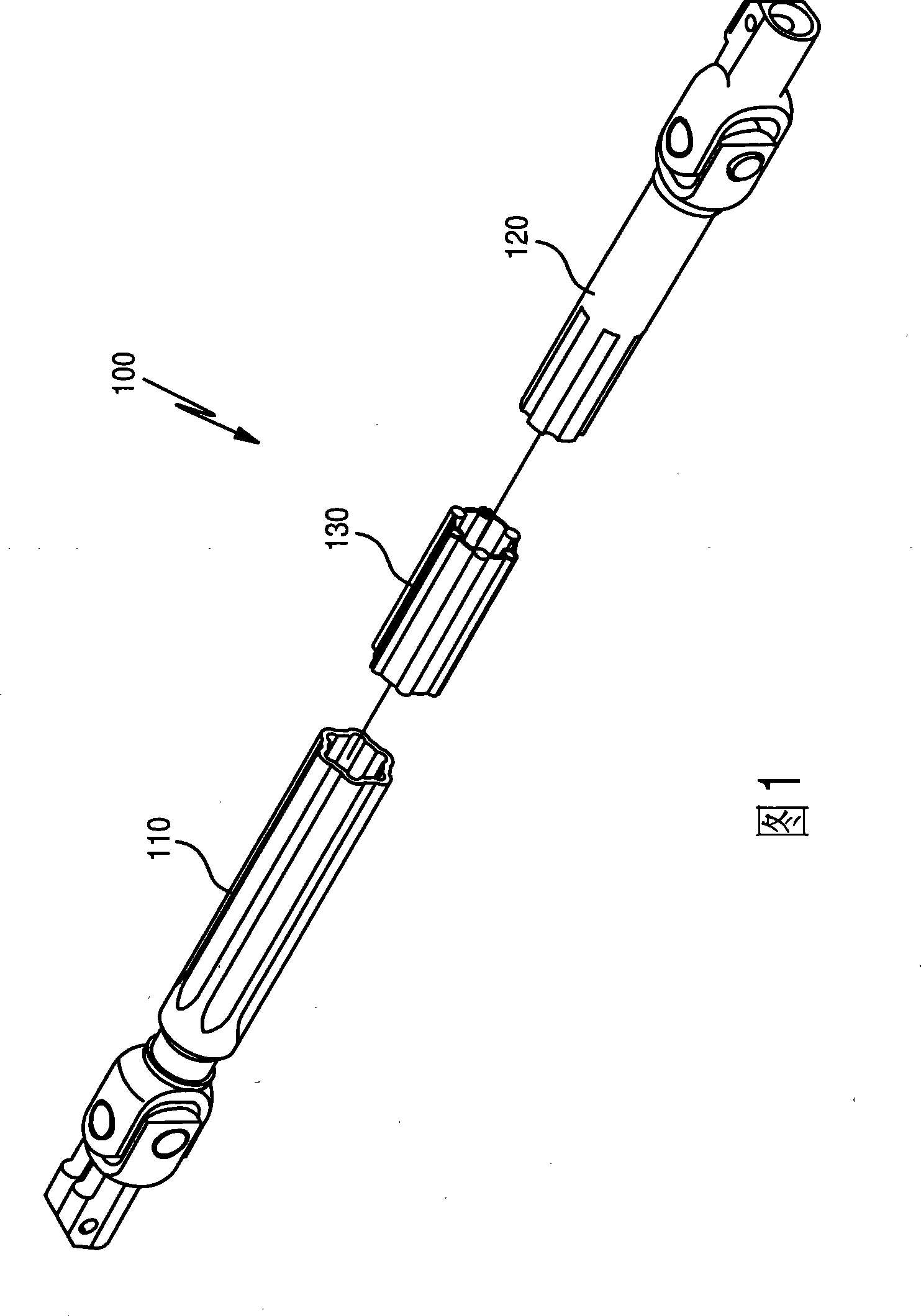
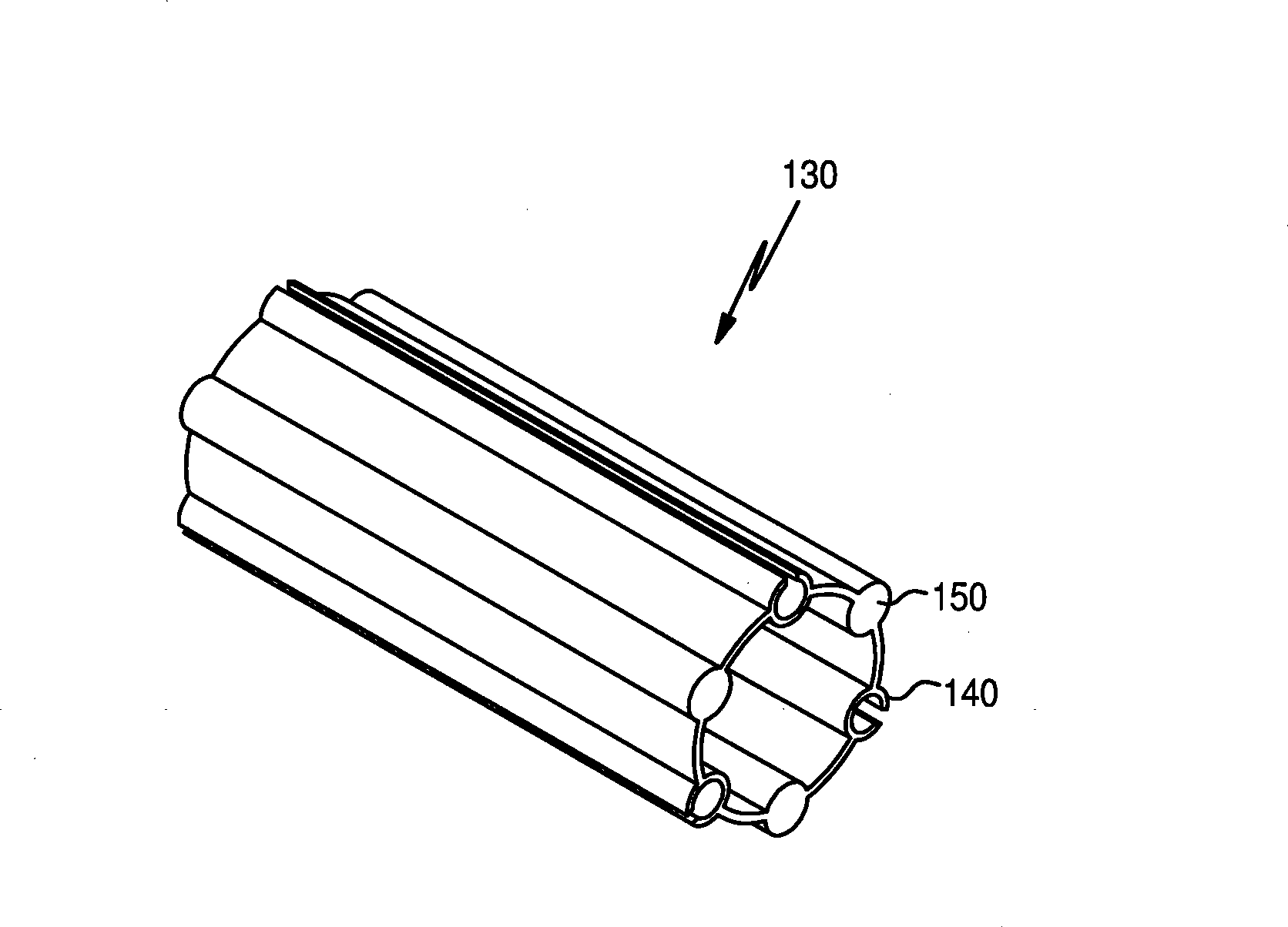
[0031] The universal joint 200 of the first embodiment of the present invention includes a shaft 210 inserted into a sliding bushing 240 , and a sleeve 220 which is hollow to accommodate the sliding bushing 240 inserted into the shaft 210 .

[0032] The shaft 210 has one end connected to a steering shaft (not shown), and the other end of the shaft 210 has a first combination recess 23...


PUM


Abstract

A universal joint includes a tube having a hollow shape; a slip bush inserted into the tube; and a shaft assembled with the tube through the slip bush, wherein the slip bush includes power transmission parts, which are arranged along an circumferential surface of the slip bush in an axial direction and have pins positioned at centers of the power transmission parts and supports supporting both ends of each pin, and elastic parts, which are arranged along the circumferential surface of the slip bush while being spaced from the power transmission parts and have a section with a C-shape, which is formed in such a manner that a side portion is cut out in the axial direction. Therefore, strength and rigidity are improved, even when twist is generated in the universal joint, so that clearance and noise due to abrasion, pressing, etc. can be minimized.

Description

technical field [0001] The invention relates to a universal joint, in particular to a sliding bush provided with a power transmission part of the universal joint. Background technique [0002] In a steering device of a vehicle, if a driver turns a steering wheel in a predetermined direction, a steering shaft connected to the steering wheel turns correspondingly. This steering shaft transmits the rotational force to a gearbox, which includes rack-pinion gears, and passes through a universal joint. At this time, the gearbox converts the rotational motion of the steering shaft into a linear motion through the rack-and-pinion gear, which is transmitted to the gear rod. The gear rod can transmit force to the tie rod connected to the steering knuckle of the wheel, so as to change the driving direction of the vehicle. [0003] More specifically, the shaft between the steering shaft and the gearbox has a structure in which an input rod and an output rod are connected to each other ...

Claims


Application Information

Patent Timeline
Patent Type & Authority Applications(China)
IPC IPC(8): B62D7/18F16D3/26
CPCF16C3/03F16D3/06
Inventor 郑暎锡朴正植
Owner HL MANDO CORP
Why Eureka
Try Eureka