Tunnel ring direction drainpipe equipped with strip heat-insulating layer

A drainage pipe and thermal insulation layer technology, which is applied in drainage, mining equipment, safety devices, etc., can solve the problems of peeling and peeling of the thermal insulation layer, failure to pay attention to the waterproof and moisture-proof of the thermal insulation layer, and high project cost, so as to achieve short distance of seepage and good drainage Outstanding effect, good heat preservation effect

Inactive Publication Date: 2009-05-20
CHANGAN UNIV
View PDF0 Cites 27 Cited by
  • Summary
  • Abstract
  • Description
  • Claims
  • Application Information

AI Technical Summary

Problems solved by technology

The disadvantage of the first method is that in the cold season, if the tunnel lining is not waterproof, water seepage will soak the insulation layer on the surface of the lining, reduce the insulation performance of the insulation layer, and gradually cause the insulation layer to peel off. the road is flowing and icy
The disadvantage of the second method is that it does not pay attention to the waterproof and moisture-proof of the insulation layer. The insulation layer is in a humid environment all the year round, and its insulation performance will be greatly reduced.
In addition, the construction techniques of the two methods are r

Method used


Image

  • Tunnel ring direction drainpipe equipped with strip heat-insulating layer
  • Tunnel ring direction drainpipe equipped with strip heat-insulating layer
  • Tunnel ring direction drainpipe equipped with strip heat-insulating layer

Examples


Embodiment Construction

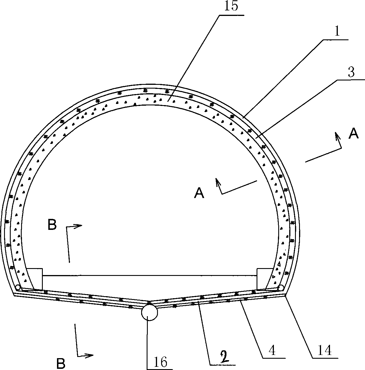
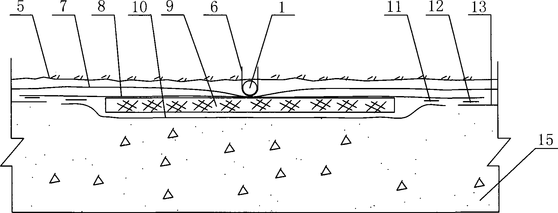
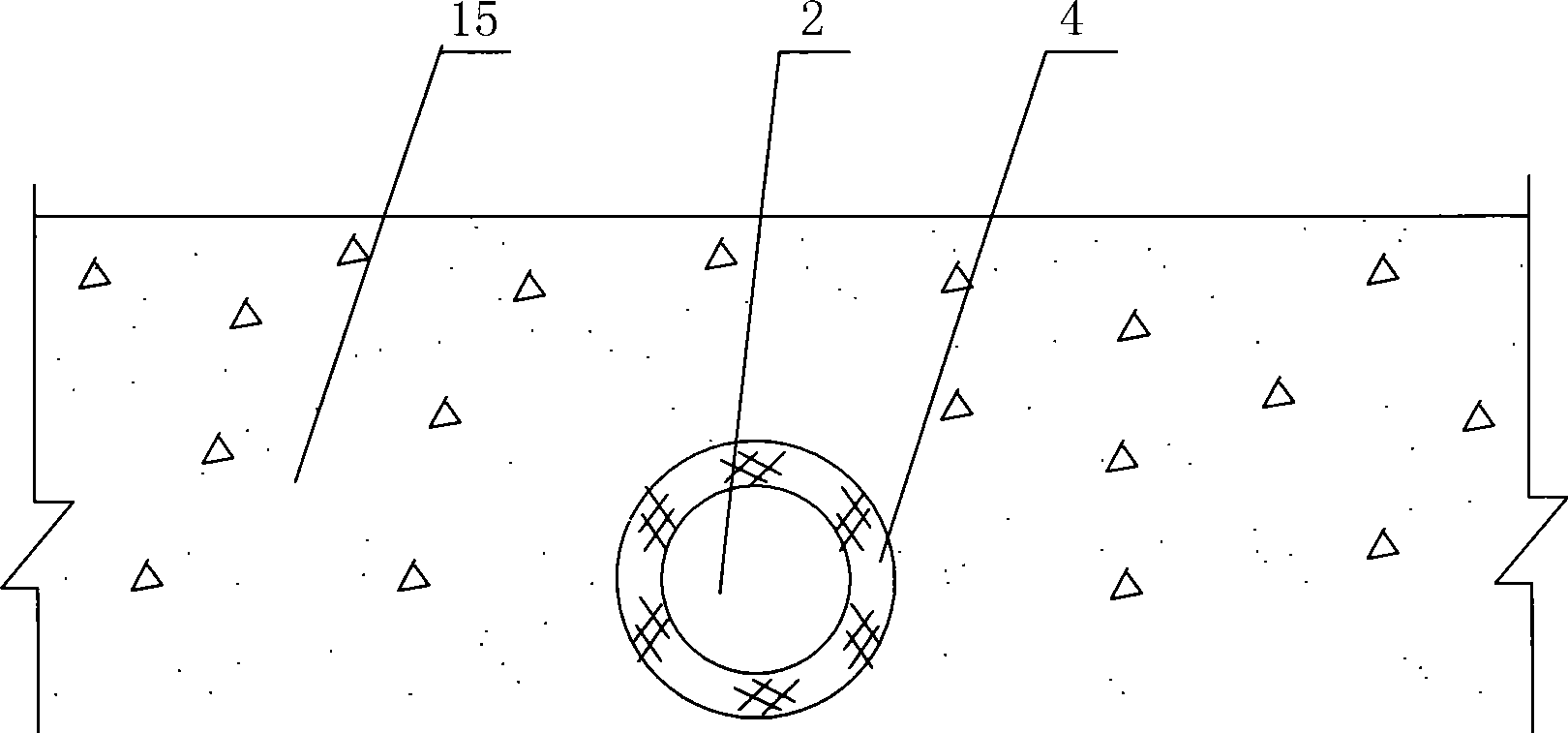
[0021] Such as figure 1 , figure 2 with image 3 As shown, the present invention includes a lining wall rear circumferential drainage pipe 1 and two road-surface circumferential drainage pipes 2 correspondingly connected to its two ends, wherein the lining wall rear circumferential drainage pipe 1 is a water-permeable pipe, and the two road surface circumferential drainage pipes The drainpipe 2 is arranged transversely under the tunnel road surface, and communicates with the circumferential drainpipe 1 behind the lining wall and the central drainpipe 16 located in the center of the tunnel. In use, the seepage water from the formation behind the lining wall of the tunnel enters the circumferential drainage pipe 1 behind the lining wall, and is directly discharged from the central drainage pipe 16 through the circumferential drainage pipes 2 under the two road surfaces. In order to prevent the circumferential drainage pipe 1 behind the lining wall from being frozen in the col...


PUM


Abstract

The invention discloses a tunnel circumferential drainage pipe provided with a band insulation layer. The tunnel circumferential drainage pipe comprises a circumferential drainage pipe behind the liner wall, and two circumferential drainage pipe which are arranged below the road surface and are connected with two ends of the circumferential drainage pipe behind the liner wall., wherein the circumferential drainage pipes behind the liner wall is a water permeable pipe, the two circumferential drainage pipe arranged below the road surface are arranged transversely and are communicated with the circumferential drainage pipe behind the lining wall and a central drainage pipe at the center of the tunnel. The band insulation layer arranged at one side of the circumferential drainage pipe behind the liner wall close to a concrete lined wall comprises two layers of waterproof boards and a heat insulation material layer between the two layers of the waterproof boards. The tunnel circumferential drainage pipe has a simple structure, low cost, and short flow distance of drainage. In addition, the heat insulation material is not soaked by stratum seeped water, and the pipe is not blocked due to icing, so the stratum seeped water behind the tunnel liner wall can be effectively and rapidly drained.

Description

technical field [0001] The invention relates to a tunnel circumferential drainage pipe, in particular to a tunnel circumferential drainage pipe provided with a strip insulation layer. Background technique [0002] Tunnels in cold regions often freeze due to the freezing of the drainage system behind the lining wall, especially the freezing of the circumferential drainage pipes, which leads to poor drainage of the tunnel and induces various tunnel freezing damages. There are two kinds of antifreeze methods for the existing tunnel circumferential drainage pipes: one is to set an insulating layer on the outer surface of the tunnel lining; the other is to set an insulating layer behind the tunnel lining wall. The disadvantage of the first method is that in the cold season, if the tunnel lining is not waterproof, water seepage will soak the insulation layer on the surface of the lining, reduce the insulation performance of the insulation layer, and gradually cause the insulation ...

Claims


Application Information

Patent Timeline
IPC IPC(8): E21F16/02
Inventor 吕康成
Owner CHANGAN UNIV
Why Eureka
Try Eureka