
Torsion amplifier

An amplifier and torque technology, applied in the direction of gear transmission, belt/chain/gear, mechanical equipment, etc., can solve the problems of not improving energy utilization rate, unable to improve driving mileage, etc., achieving simple structure and reducing matching power , the effect of improving driving force

Inactive Publication Date: 2009-05-20
毕海军
View PDF0 Cites 0 Cited by
  • Summary
  • Abstract
  • Description
  • Claims
  • Application Information

AI Technical Summary

Problems solved by technology

Therefore, there is still no device that can keep its input and output speeds constant and increase its torque, that is, a torque amplifier, for use, so that the current energy utilization rate cannot be improved all the time. The equipment used as power cannot improve the driving range, so developing a torque amplifier has become a top priority

Method used


Image

  • Torsion amplifier
  • Torsion amplifier
  • Torsion amplifier

Examples


Embodiment 1

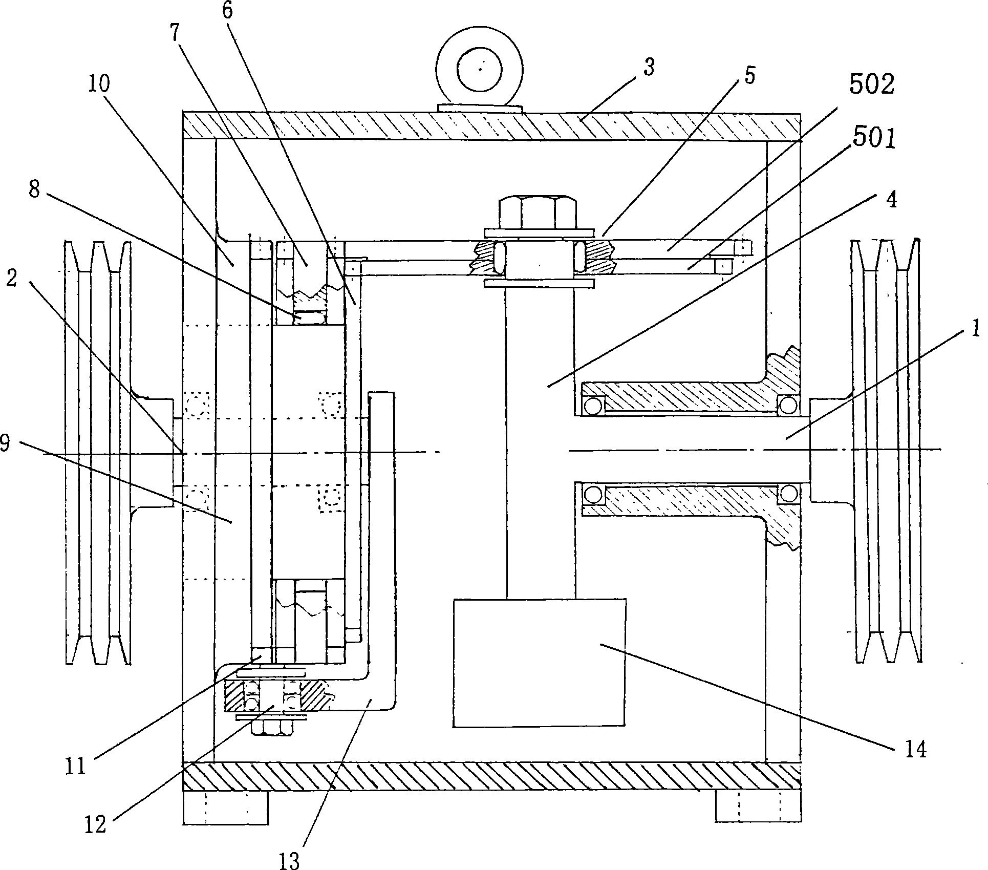
[0027] Such as figure 1 shown.

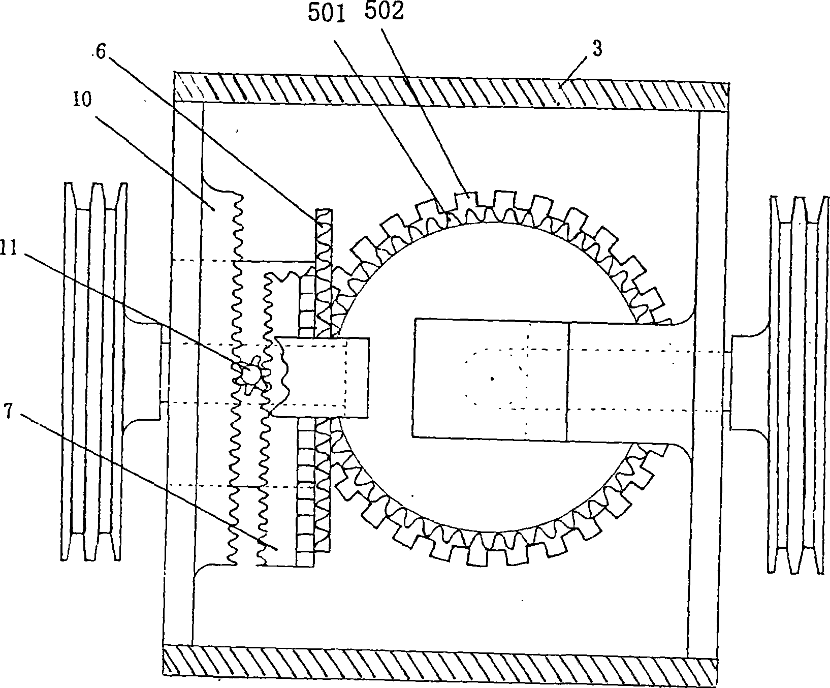
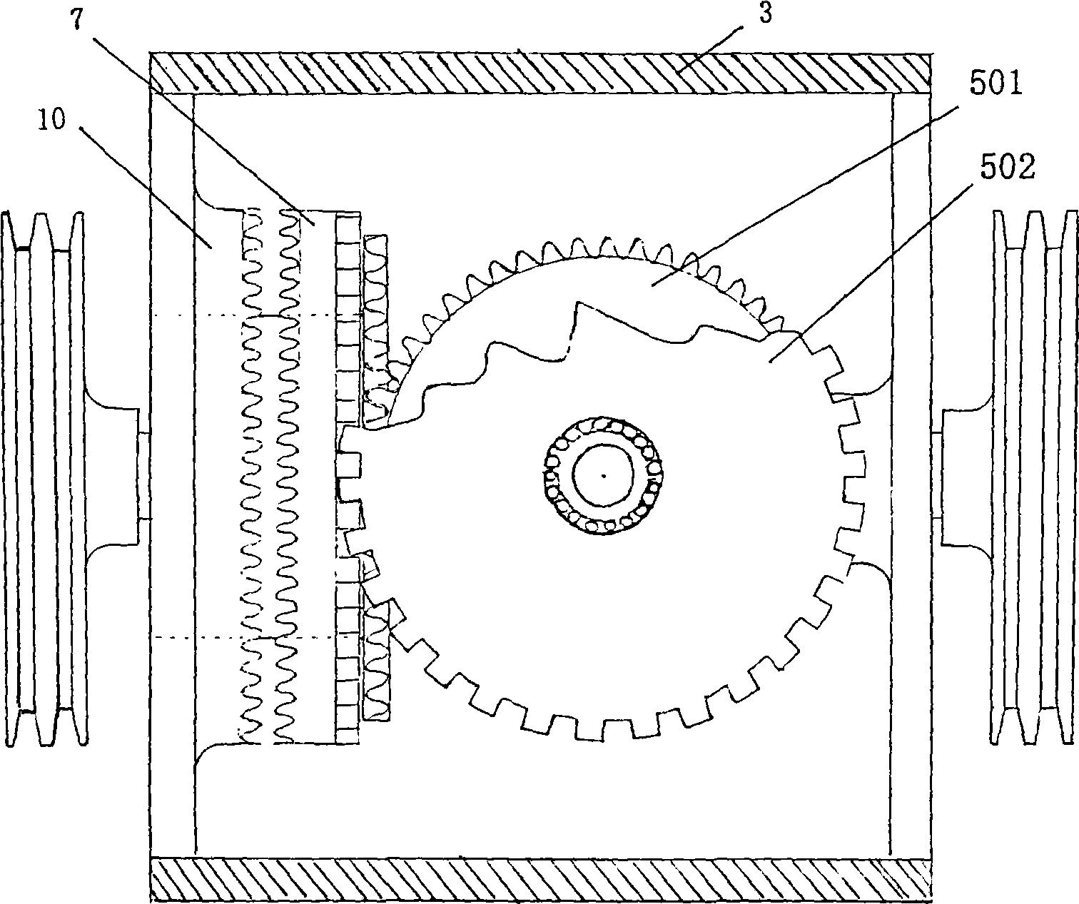
[0028] A kind of torque amplifier, it comprises input shaft 1, output shaft 2, frame 3, as figure 1 , one end of the input shaft 1 located in the frame 3 is vertically connected with a transmission shaft 4, a double gear 5 is installed on one end of the transmission shaft 4, a balance weight 14 is installed on the other end, and the pinion in the double gear 5 501 meshes with the small sun gear 6 fixed in the frame 3 on one side of the output shaft 2, and the large gear 502 in the double gear 5 meshes with a gear in the double row gear 7, as image 3 As shown, the double row gear 7 is installed on the fixed shaft 9 through the bearing 8, and one end of the fixed shaft 9 is fixedly connected with the frame 3, and the aforementioned small sun gear 6 is fixed on the fixed shaft 9, and is close to the A large sun gear 10 with the same outer diameter as the double row gear 7 is fixedly installed on one side of the output shaft 2, and a large sun g...

Embodiment 2

[0033] As shown in Figure 4 and 5.

[0034] A kind of torque amplifier, it comprises input shaft 1, output shaft 2, frame 3, input shaft 1 is positioned at one end in frame 3 and is vertically connected with drive shaft 4, and bevel gear 15 and bevel gear 15 and There is a dowel bar 16 with a one-way rotation mechanism, and a balance weight 14 is installed on the other end (the same bevel gear and a dowel bar can also be installed). One end of the dowel bar 16 is movably inserted on the force plate 17, One end of the force plate 17 is fixed on the output shaft 2; the sun gear 18 which is also a bevel gear meshed with the bevel gear 15 is fixedly installed in the frame 3 positioned at one side of the output shaft 2 . As shown in Figure 4. The one-way rotation mechanism described herein can be a one-way bearing, which is installed between the dowel rod 16 and the transmission shaft 4; Figure 5 shown in the mechanism to be implemented, Figure 5 The one-way rotation mechanism...


PUM


Abstract

The invention provides a torque amplifier, and belongs to the technical field of mechanical transmission. The torque amplifier is characterized in that the torque amplifier comprises an input shaft(1), an output shaft(2) and a frame(3), wherein the input shaft(1) is arranged at one end of the frame(3) and vertically connected with a transmission shaft(4), one end of the transmission shaft(4) is provided with a bevel gear(15) and a force conduction bar(16) provided with an unidirectional rotation gear, one end of the force conduction bar (16) is movably inserted in a force conduction plate(17), and one end of the force conduction plate(17) is fixed on the output shaft(2); and the part of the frame(3), which is arranged on the side of the output shaft(2), is fixedly provided with a sun gear(18) which is also a bevel gear and meshed with the bevel gear(15). Moreover, the invention also discloses a torque amplifier with a different structure, which belongs to the same technical conception. The torque amplifier solves the long-existing problem that the torque can not be increased under conditions of equal velocity, and also has the advantages of big increasing range of the torque, simple structure and wide application range.

Description

technical field [0001] The invention relates to a mechanical booster, in particular to a driving device capable of amplifying torque to realize the purpose of a small horse-drawn cart, in particular a torque amplifier. Background technique [0002] As we all know, the principle of leverage can be used to magnify the strength of the human body. As long as the fulcrum is suitable, people can lift heavy objects that exceed their own strength by dozens or even thousands or tens of thousands of times. [0003] In modern mechanical equipment, in order to rotate large rotating equipment, people either equip with a more powerful driving device, or use a speed reduction mechanism to increase the torque to drive the rotation of large equipment. Therefore, there is still no device that can keep its input and output speeds constant and increase its torque, that is, a torque amplifier, for use, so that the current energy utilization rate cannot be improved all the time. The driving rang...

Claims


Application Information

Patent Timeline
Patent Type & Authority Applications(China)
IPC IPC(8): F16H37/12F16H1/28
Inventor 毕海军
Owner 毕海军
Learn More