Low-pollution concentrating heat storage cremating apparatus

A low-pollution, heat storage technology, applied in incinerators, lighting and heating equipment, combustion methods, etc., can solve problems such as fines, high VOC concentration in exhaust gas, and failure to pass environmental air pollution standards.

Active Publication Date: 2009-05-20
DESICCANT TECH CORP +1
View PDF0 Cites 19 Cited by
  • Summary
  • Abstract
  • Description
  • Claims
  • Application Information

AI Technical Summary

Problems solved by technology

[0007] However, the above-mentioned concentrated heat storage incineration device 10 needs to alternately switch heat storage between the first regenerator 14a and the second regenerator 14c, the first valve part 22a, the second valve part 22b, the third valve part 22c, the The four valves 22d will be fully open for a short time during the switching process, because the impedance (pressure loss) of the exhaust gas passing through the first heat storage chamber 14a or the second heat storage chamber 14b is relatively large, so during this switching period, the exhaust gas will not Pass through the first heat storage chamber 14a, the second heat storage chamber 14c or the heating chamber 14b and directly flow to the exhaust chimney 20, resulting in a significant increase in the VOC concentration of the exhaust gas discharged from the concentrated heat storage incineration device 10 (close to the VOC concentration at the exhaust gas inlet) Generate a concentration spike (peak)
Assuming that the destruction efficiency of burning VOC is 98%, the usual emission concentration is 2% of the inlet value, but when the valve group is switched, the VOC emission concentration is close to the inlet concentration value (100%), that is, the emission concentration instantly becomes 50 times the usual value , not only reduces the overall efficiency of exhaust gas treatment, but if the concentration monitoring just detects the point where the surge occurs, it will also cause the exhaust gas VOC concentration measurement value to be too high, which may fail to pass the environmental protection air pollution standard and be fined
[0008] Therefore, there is the invention of the three-tower regenerative incinerator or the rotary valve type regenerative incinerator to improve the above-mentioned VOC concentration surge problem, but the disadvantage of the three-tower regenerative incinerator or the rotary valve type regenerative incinerator is that the cost is too high high

Method used


Image

  • Low-pollution concentrating heat storage cremating apparatus
  • Low-pollution concentrating heat storage cremating apparatus
  • Low-pollution concentrating heat storage cremating apparatus

Examples


Embodiment Construction

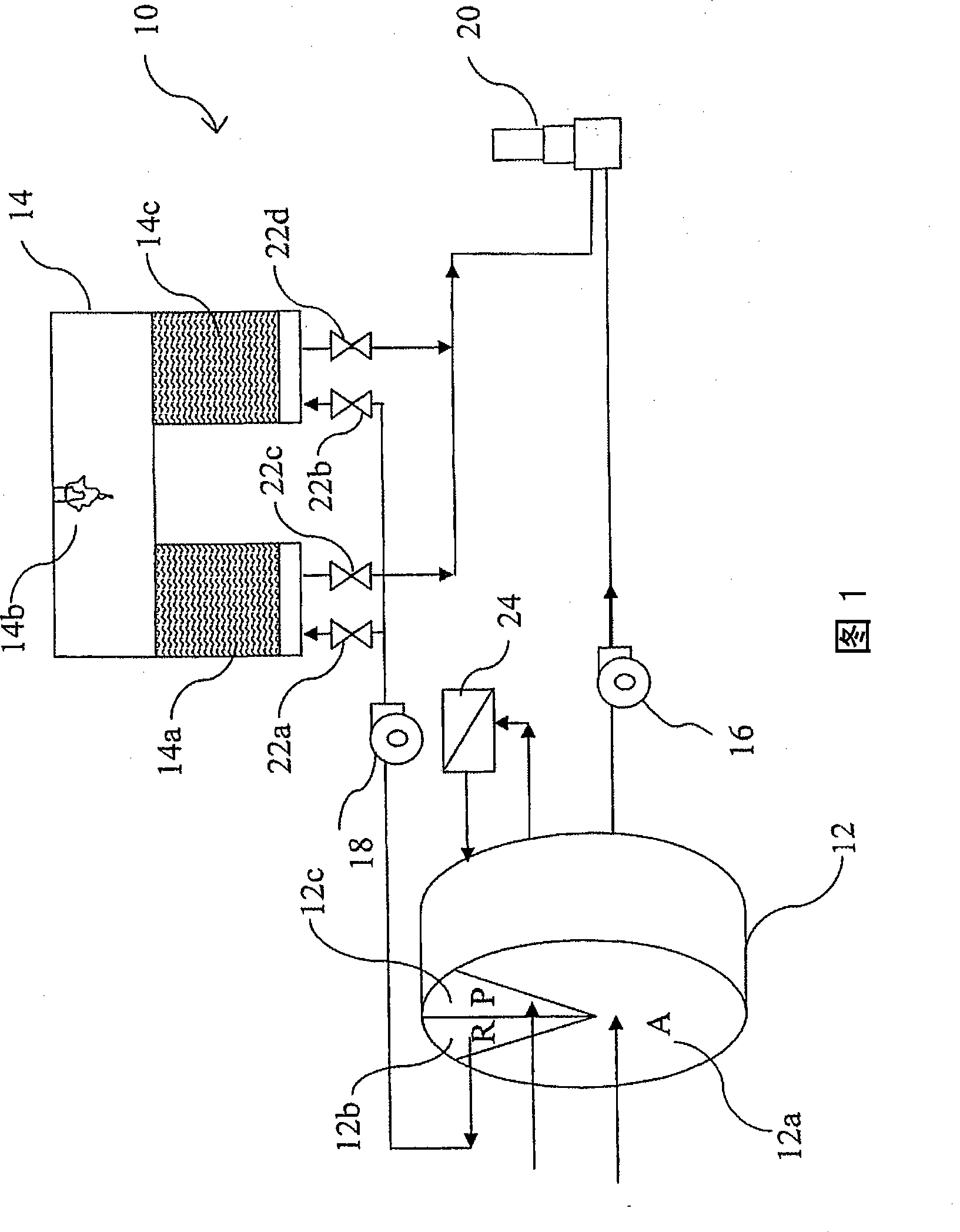
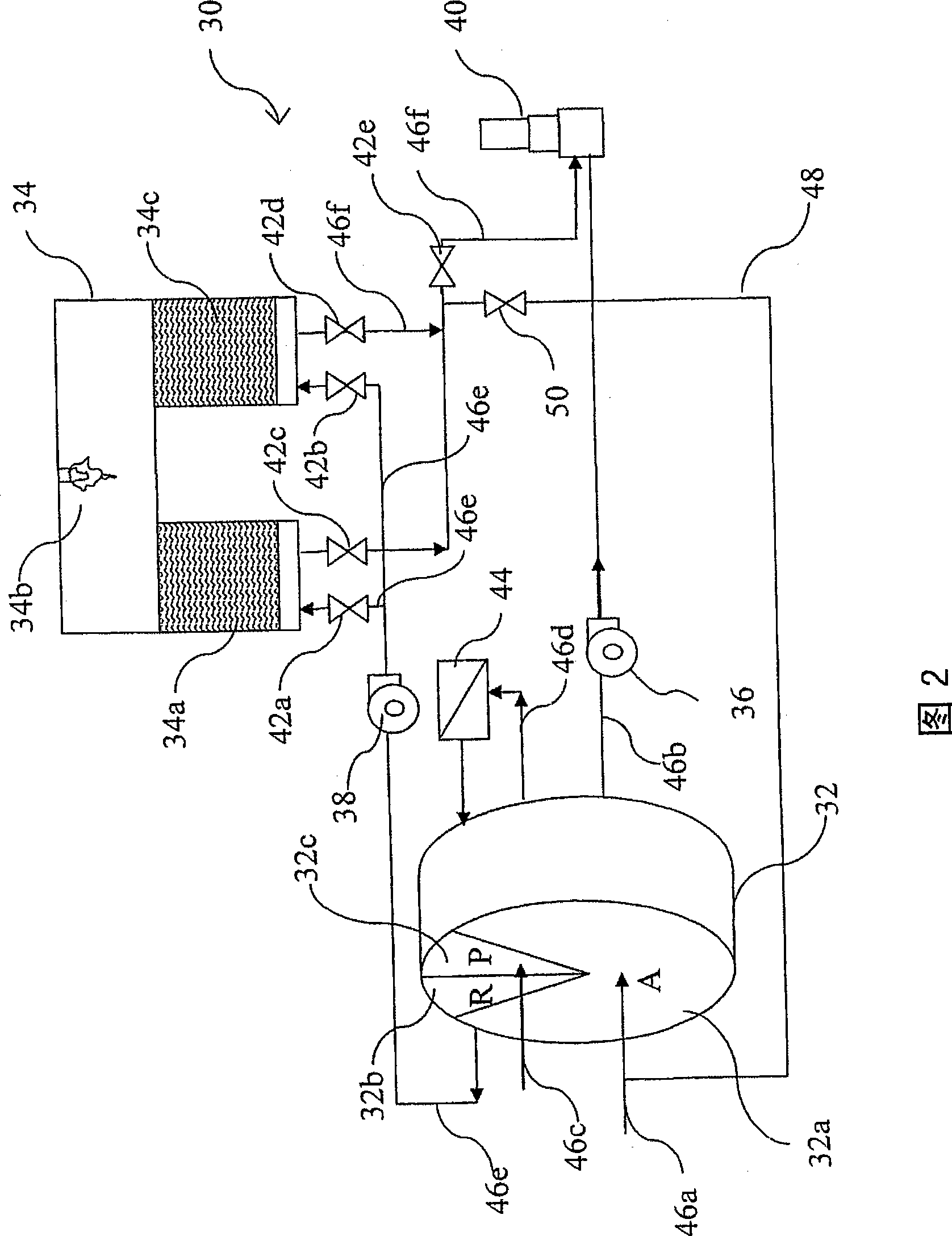
[0043] Fig. 2 is a schematic structural view of the present invention, as shown in the figure, the concentrated heat storage incinerator 30 mainly includes a zeolite runner 32, a regenerative incinerator 34, a pipeline group and a recovery pipeline group, and the zeolite runner 32 has adsorption zone 32a, desorption zone 32b and cooling zone 32c, while the regenerative incinerator 34 has a first regenerator 34a, a heating chamber 34b and a second regenerator 32c, and the pipeline group includes a pipe fitting group and a valve fitting group, wherein The pipe set includes a first pipe 46a, a second pipe 46b, a third pipe 46c, a fourth pipe 46d, a fifth pipe 46e and a sixth pipe 46f, and the valve set includes a first valve 42a, a second valve 42b, a The three valve parts 42c, the fourth valve part 42d and the fifth valve part 42e, the recycling pipeline set includes a recycling pipe part 48 and a recycling valve part 50, and the valve part group and the recycling valve part 50 a...


PUM


Abstract

The invention provides a low-pollution device for condensing, accumulating heat and incinerating, which comprises a zeolite rotating wheel, a heat accumulating type incinerator, a pipeline group and a recycling pipeline group. The zeolite rotating wheel is used for condensing waste gas; the heat accumulating type incinerator can be used for combusting the waste gas; the pipeline group comprises a pipe fitting group communicated with the zeolite rotating wheel, the heat accumulating type incinerator and a discharge chimney, and a valve group for controlling circulation of internal gas in the pipe group; and the recycling pipeline group is connected with the pipeline group to assist recycling of the discharged waste gas. The device utilizes self differential pressure power to recycle and treat high VOC-concentration waste gas discharged when valve members are switched, so as to achieve the effects of improving treating efficiency of the waste gas and reducing environmental pollution.

Description

technical field [0001] The invention relates to a low-pollution waste gas concentration and incineration device, in particular to a concentration heat storage incineration device that can improve the treatment efficiency of organic waste gas. Background technique [0002] The semiconductor manufacturing and optoelectronic industries will emit a large amount of waste gas containing volatile organic compounds (Volatile Organic Compounds). Therefore, the Environmental Protection Air Pollution Regulations has set the exhaust gas VOC removal efficiency standard to reduce the harm of VOC to the environment. Due to the large amount of waste gas emissions from semiconductor manufacturing and optoelectronic industries, the composition is complex (mixture of organic substances with high and low boiling points, such as IPA, Acetone, PGME, PGMEA, etc.) and the emission is in the low to medium range (50-1000ppm of CH4 ), which makes it difficult to choose an appropriate waste gas treatme...

Claims


Application Information

Patent Timeline
IPC IPC(8): F23G7/06
Inventor 郑石治扶亚民魏新朕徐瑞珠刘邦昱洪守铭
Owner DESICCANT TECH CORP
Why Eureka
Try Eureka