
Microelectronic sensor device for concentration measurements

A sensor device, microelectronics technology, applied in the direction of measuring device, magnetic variable measurement, magnetic performance measurement, etc., can solve the problems of measurement signal destruction, low concentration of target substances, etc., and achieve high-precision results

Inactive Publication Date: 2009-05-20
KONINKLIJKE PHILIPS ELECTRONICS NV
View PDF2 Cites 4 Cited by
  • Summary
  • Abstract
  • Description
  • Claims
  • Application Information

AI Technical Summary

Problems solved by technology

The problem with these and similar biosensors is that the concentration of the target substance is usually very low and the measurement signal is thus severely corrupted by different noise sources

Method used


Image

  • Microelectronic sensor device for concentration measurements
  • Microelectronic sensor device for concentration measurements
  • Microelectronic sensor device for concentration measurements

Examples


Embodiment Construction

[0056] The same reference numbers or numbers that differ in the hundreds place refer to the same or similar parts throughout the figures.

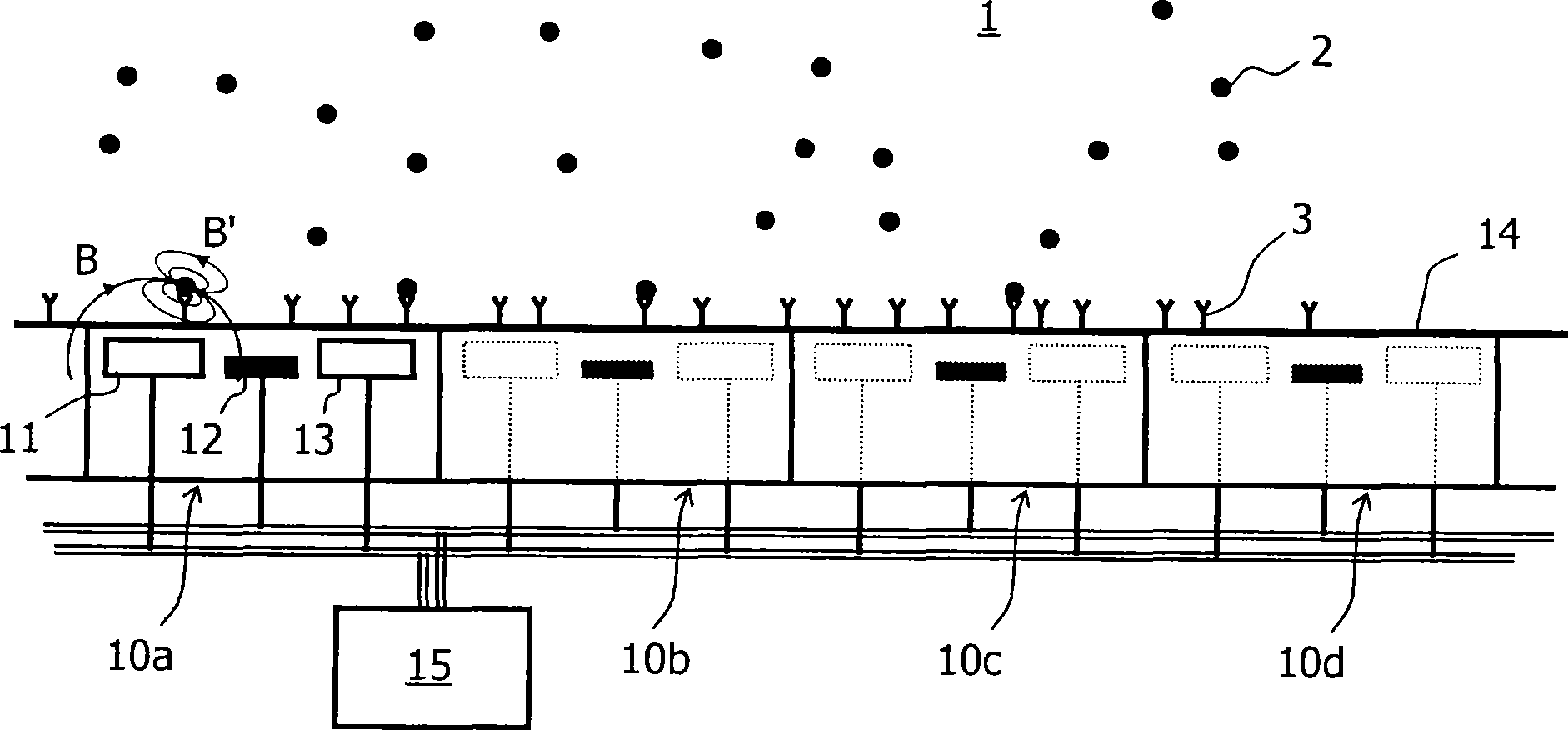
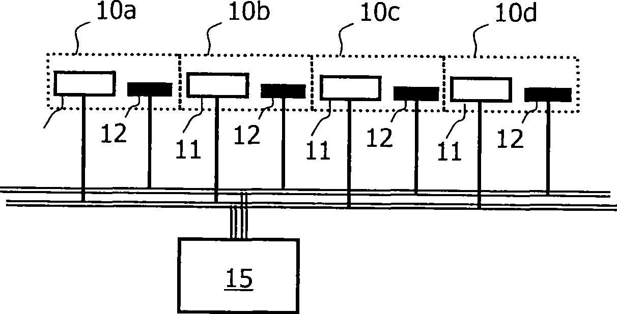
[0057] figure 1 A microelectronic biosensor according to the invention is shown, consisting of an array of (eg 100) sensor cells 10a, 10b, 10c, 10d, etc. The biosensor can eg be used to measure the concentration of target particles 2 (eg proteins, DNA, amino acids, drugs) in a sample solution (eg blood or saliva). In one possible example of a binding scheme, this is achieved by providing the sensing surface 14 with a first antibody 3 to which the target particles 2 can bind. For the sake of brevity, it is assumed here that the target particles that must be analyzed have been labeled (ie magnetic particles or beads attached) so that they can be tracked. Whether this is the case depends on the biochemical assay used. The excitation current flowing into the wires 11 and 13 of the sensor unit 10a generates a magnetic field B which magnetize...


PUM


Abstract

The invention relates to a method and a magnetic sensor device for the determination of the concentration of target particles (2) in a sample fluid, wherein the amount of the target particles (2) in a sensitive region (14) is observed by sampling measurement signals with associated sensor units (10a-10d). The target particles (2) may optionally be bound to binding sites (3) in the sensitive region, and a parametric binding curve, e.g. a Langmuir isotherm, may be fitted to the sampled measurement signals to determine the desired particle concentration in the sample. Moreover, parameters like the sampling rate and the size of the sensitive region (14) can be dynamically fitted during the ongoing sampling process to improve the signal-to-noise ratio. In another embodiment of the invention, single events corresponding to the movement of target particles into, out of, or within the sensitive region are detected and counted.

Description

technical field [0001] The present invention relates to a method and a microelectronic sensor device for determining the number of target particles in a sample, wherein the number of target particles in a sensing area is measured. Furthermore, it relates to a magnetic sensor device for detecting magnetized particles. Background technique [0002] A microelectronic magnetic sensor device is known from WO 2005 / 010543 A1 and WO 2005 / 010542 A2, which are incorporated herein by reference, for example, which can be used in microfluidic biosensors for the detection of molecules, for example with Magnetic beads labeled biomolecules. The microsensor device has an array of sensor cells including wires for generating a magnetic field and giant magnetoresistance (GMR) for detecting stray fields generated by magnetic beads. The GMR signal then indicates the number of beads in the vicinity of the sensor unit. The problem with these and similar biosensors is that the concentration of th...

Claims


Application Information

Patent Timeline
IPC IPC(8): G01N33/543G01N35/00
CPCG01R33/093G01R33/1269G01N27/745B82Y25/00
Inventor J·H·尼乌文赫伊斯H·范佐恩J·A·H·M·卡尔曼J·维恩B·M·德布尔T·P·H·G·扬森
Owner KONINKLIJKE PHILIPS ELECTRONICS NV
Learn More