Portable ultrasonic diagnostic device

An ultrasonic diagnostic instrument, portable technology, applied in sonic diagnosis, infrasonic diagnosis, ultrasonic/sonic/infrasonic diagnosis, etc. It can solve the problem that the center of gravity of the machine is biased towards the power board, the interference is difficult to be completely eliminated, and the image quality is reduced. It achieves a compact structure, Improve image output quality and strong anti-interference ability

Active Publication Date: 2009-05-27
SHENZHEN MINDRAY BIO MEDICAL ELECTRONICS CO LTD
View PDF0 Cites 14 Cited by
  • Summary
  • Abstract
  • Description
  • Claims
  • Application Information

AI Technical Summary

Problems solved by technology

In this existing architecture, the power board and the probe board are relatively close in space, making it difficult to completely eliminate the interference of the power board to the probe board, and the analog echo of the probe board is very sensitive to interference; the connecting cable between the main board and the probe board is long , across the main frame, power supply board and CRT driver board, the signal is easy to be interfered; the above will cause the image quality to degrade
In addition, because the power board is relatively heavy, the power board and the probe board are placed on one side, and the main board is on the opposite side, which will cause the center of gravity of the machine to be biased to one side of the power board.

Method used


Image

  • Portable ultrasonic diagnostic device
  • Portable ultrasonic diagnostic device

Examples


Embodiment 1

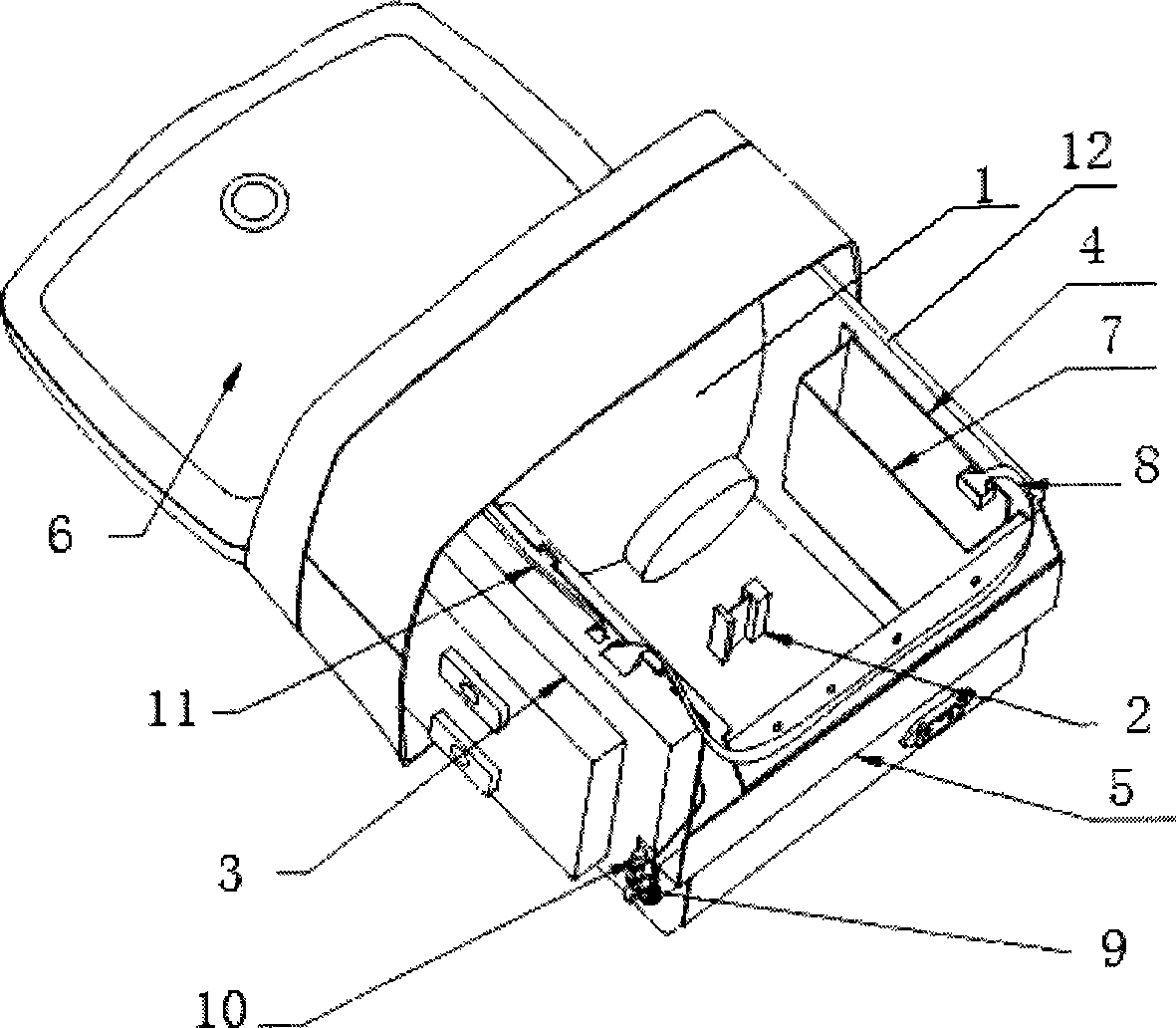
[0019] Please refer to figure 1 As shown, the portable ultrasonic diagnostic instrument of this example includes a main frame 12, a CRT picture tube 1, a CRT driver board 2, a main board and a probe board assembly 3, a power board 4, an input and output interface board 5, a keyboard board 6, and the like. Picture tube 1 and CRT driver board 2 are installed on the main frame 12, and CRT driver board 2 is horizontally placed below picture tube 1, is connected with main board with shielded cable 10; size.

[0020] The functional board is designed as compactly as possible on the basis of the main frame 12 .

[0021] The main board probe board assembly 3 and the power board 4 are vertically placed on both sides of the main frame 12, spaced as far as possible to reduce the possibility of radiation coupling; the single board of the power board 4 is relatively heavy, and its weight is equivalent to that of the main board probe board assembly 3. The two are symmetrically placed to ma...

Embodiment 2

[0026] figure 1 The power supply board and power supply shield are on the inside of the main frame sheet metal; in this example, move them to the outside of the main frame sheet metal, so that the power supply board is farther away from the main board, probe board and CRT picture tube, and the main frame sheet metal is also It will play a certain shielding role, and the interference will be lower.


PUM


Abstract

The invention discloses a portable ultrasonic diagnostic apparatus which comprises a main frame, a CRT kinescope, a CRT drive plate, a power panel, a mainboard and a probe plate. The CRT kinescope and the CRT drive plate are installed on the main frame. The power panel is arranged at one side of the main frame vertically. The mainboard and the probe plate are arranged at the other side of the main frame vertically. As the proposal is adopted, a mainboard and probe plate component is apart from the power panel in space, thereby reducing space radiation coupling and improving image output quality. The mainboard and probe plate component and the power panel are arranged symmetrically and are as close as possible in weight, thereby ensuring the gravity center of a whole machine is balanced. The mainboard and the probe plate are connected from board to plate instead of cable, and the mainboard and the probe plate are piled up and shielded, thereby ensuring a compact structure and also avoiding the mutual interference between the mainboard and the probe plate and the interference caused by the connection by a long cable. The whole machine has compact and stable structure, strong anti-interference capacity and good image quality.

Description

【Technical field】 [0001] The invention relates to a structure of a portable ultrasonic diagnostic instrument. 【Background technique】 [0002] Ultrasound imaging is a non-invasive and cheap medical imaging diagnostic method, which is widely used in the examination of various parts of the body, such as the examination of abdominal organs and obstetrics and gynecology. With the rapid development of electronic technology and the improvement of integration, ultrasonic diagnostic systems are becoming more and more miniaturized for portability. However, integrating complex ultrasound systems in a compact space, interference and heat dissipation have brought challenges to the architecture of the whole machine. As a portable ultrasonic diagnostic system, compact and light structure is the basic requirement, but the compact structure brings the problem of interference; the analog echo signal of ultrasound is often amplified hundreds or even thousands of times, so The problem of inte...

Claims


Application Information

Patent Timeline
Patent Type & Authority Applications(China)
IPC IPC(8): A61B8/00H05K7/20G12B15/00
Inventor 姚海锋彭国庆高清山
Owner SHENZHEN MINDRAY BIO MEDICAL ELECTRONICS CO LTD
Why Eureka
Try Eureka