Machine for threading tube body

A wire turning machine and tube body technology, applied in turning equipment, turning equipment, metal processing machinery parts, etc., can solve the problems of small quantity, difficult assembly and maintenance, poor geometric accuracy of machine tools, etc.

Inactive Publication Date: 2009-05-27
辽宁广联机械科技有限公司
View PDF0 Cites 3 Cited by
  • Summary
  • Abstract
  • Description
  • Claims
  • Application Information

AI Technical Summary

Problems solved by technology

[0002] At present, in the field of mechanical processing technology, some manufacturers use special CNC machine tools produced by companies such as Kolinai for special CNC machine tools that are specially used for pipe and casing threads. The structure of this machine tool combines the integrated structure of the spindle and the chuck. It is complicated, and it is difficult to assemble and maintain. In addition, the num

Method used


Image

  • Machine for threading tube body
  • Machine for threading tube body

Examples


Embodiment Construction

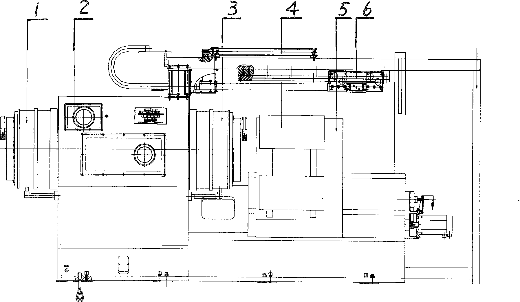
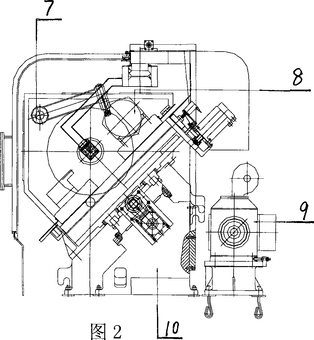
[0010] Referring to the accompanying drawings, the pipe body threading machine, the whole device consists of a rear chuck 1, a spindle box 2, a front chuck 3, a transverse slide 4, a longitudinal slide 5, a tube expander 6, a tube retainer 7, a cutter 8, and a motor 9 1. The bed 10 is composed of a headstock 2 installed on the upper left part of the bed 10. The headstock 2 is installed on the joint surface of the left part of the bed 10 inclined at 45°. The gear rotates the motor 9 of the main shaft. The front chuck 3 and the rear chuck 1 are respectively installed at the two ends of the main shaft in the headstock 2. The tube expander 6 is installed on the beam of the headstock 2. A longitudinal slide 5 for longitudinal movement, two horizontal slides 4 are installed on the two guide rails above the longitudinal slide 5, knives 8 are respectively installed on the two horizontal slides 4, and the pipe stopper 7 for the axial positioning device of the pipe is installed on the o...


PUM


Abstract

A pipe-threading machine pertains to the technical field of mechanical processing, comprising a rear chuck, a main spindle box, a front chuck, a horizontal sliding plate, a vertical sliding plate, a tube expander, a pipe block, a knife tool, a motor and a bed piece; the main spindle box is arranged at the left upper part of the bed piece; the main spindle box is arranged on the combining surface, which inclines for 45 degrees at the left part of the bed piece; the rear left part of the bed piece is provided with a motor which drives the main shaft to rotate by a tooth-shaped belt and a gear; the two ends of the main shaft in the main spindle box are respectively provided with the front chuck and the rear chuck; the tube expander is arranged on the beam of the main spindle box; the bed piece is provided with a vertical sliding plate which moves vertically along a guide rail; the two guide rails on the vertical sliding plate are provided with two horizontal sliding plates and the two horizontal sliding plates are respectively provided with knife tools. The device of the pipe-threading machine is rationally designed; the main shaft and the chucks are split structures; the hilt system can synchronously process two knives or four knives; geometric accuracy of the machine tool is better due to a heavy-duty linear guide rail; and reliability of the hydraulic piece, the front chuck and the rear chuck is enhanced.

Description

Technical field: [0001] The invention relates to a special-purpose numerical control machine tool in the field of mechanical processing technology, which is specially used for threading of pipes and casings. The types of thread processed include round buttons, partial trapezoidal buttons and special button types. Background technique: [0002] At present, in the field of mechanical processing technology, some manufacturers use special CNC machine tools produced by companies such as Kolinai for special CNC machine tools that are specially used for pipe and casing threads. The structure of this machine tool combines the integrated structure of the spindle and the chuck. It is complicated, and it is difficult to assemble and maintain. In addition, the number of knives used for simultaneous processing is small. The use of steel guide rails makes the geometric accuracy of the machine tool poor, and maintenance is inconvenient. There are also some problems in the use of hydraulic p...

Claims


Application Information

Patent Timeline
IPC IPC(8): B23B5/46B23B17/00B23B19/00B23Q3/12
Inventor 葛征宇
Owner 辽宁广联机械科技有限公司
Why Eureka
Try Eureka