
Method and apparatus for reducing coiling resistance of coiler

A technology of coiling machine and resistance, which is applied in the direction of coiling strips, transportation and packaging, and thin material processing, etc. It can solve the problems of loss of power, large resistance, and affecting coiling quality, etc.

Active Publication Date: 2009-05-27
SHANGHAI FORWARD MASCH CO LTD
View PDF0 Cites 4 Cited by
  • Summary
  • Abstract
  • Description
  • Claims
  • Application Information

AI Technical Summary

Problems solved by technology

In order to ensure the improvement of the coiling quality, the coils are very compact and neat, so the shaft pressure device and the surface pressure device are designed during the coiling process, and the direction of the surface pressure is along the straight line of the second cage Direction warping mandrel directly acts on the take-up wheel with 100% full positive pressure, resulting in a large resistance during the take-up process, affecting the quality of the take-up and losing more power

Method used


Image

  • Method and apparatus for reducing coiling resistance of coiler

Examples


Embodiment Construction

[0011] Below in conjunction with embodiment and accompanying drawing, the present invention will be further described:

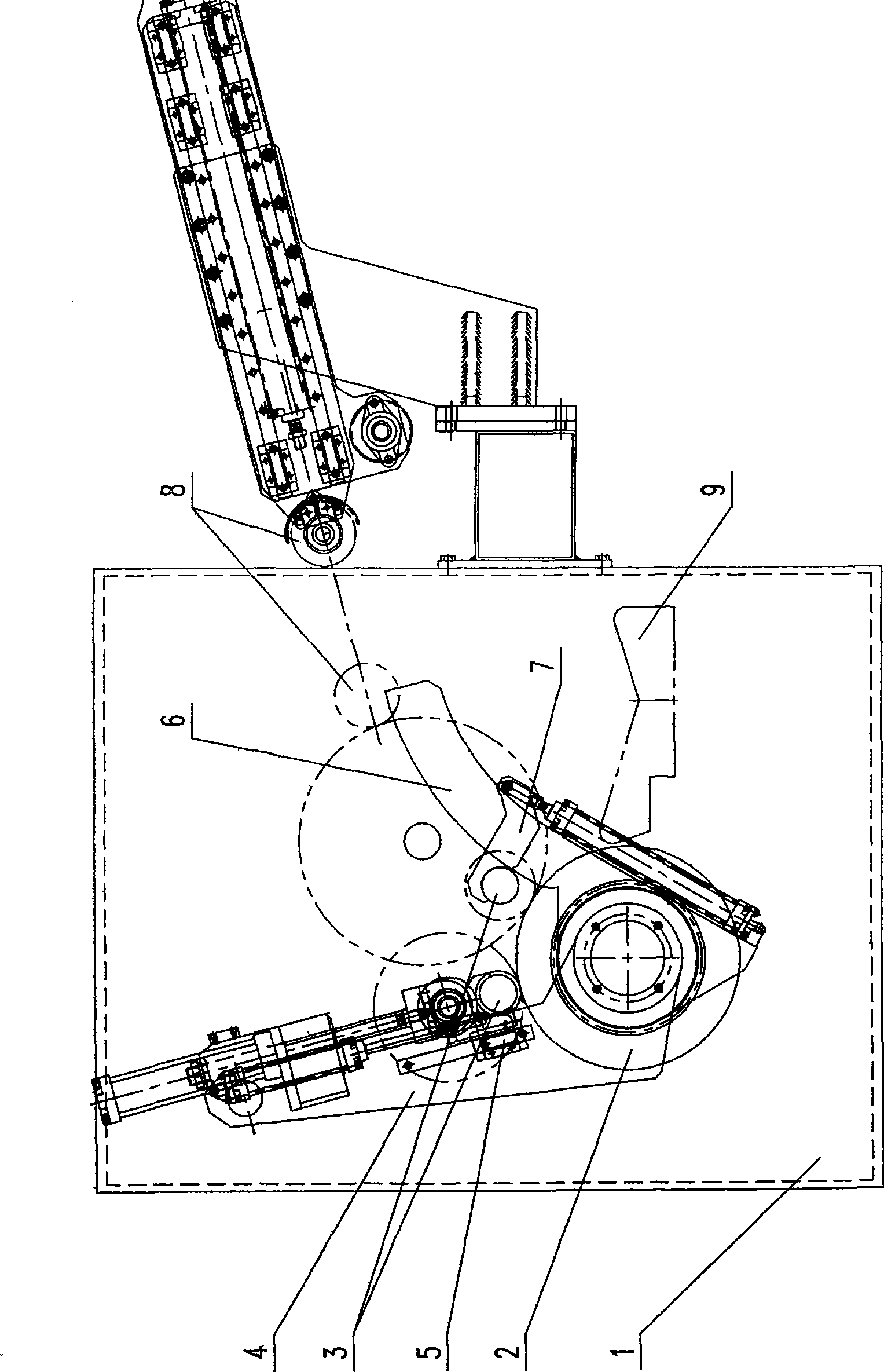
[0012] A coiling device in calendering equipment for producing plastic films with a width of 1500 mm, the device is composed of the structure according to the attached drawings, including: support wall 1, coiling wheel 2, winding mandrel 3, first cage 4, second A cage shaft pressing device 5 , a second cage 6 , a second cage shaft pressing device 7 , a second cage surface pressing device 8 and a platform 9 . Among them: the two ends of the coiling wheel 2 with a diameter of 450 mm and a wheel surface length of 1750 mm are fixed on the support wall 1 with an inner width of 2390 mm, and the first cage 4 and the parabolic second cage 6 are respectively fixed on the coiling wheel 2 When the coiling operation is performed, the coiling wheel 2 is rotated by an external power source, the first cage shaft pressurizing device 5 is fixed on the first cage 4, the press...


PUM

PropertyMeasurementUnit
Roll diameteraaaaaaaaaa

Abstract

The invention provides a method and device for reducing reeling resistance of a reeling machine. The prior reeling device is unreasonable in structure, and can generate larger resistance in the reeling process. The technical proposal of the invention comprises: a structural shape of a second holding frame in the prior reeling device is improved from the original straight line type to the parabola type, so that the forced directions of a reeling wheel are separated to reduce the reeling resistance. The method and the device have the advantages that the parabola type holding frame replaces the straight line type holding frame, force applied to the face is partially separated to the holding frame, thereby avoiding the force from being completely applied to the reeling wheel, reducing the reeling resistance, effectively utilizing dynamic force, reducing probability of damaging the reeling wheel, improving reeling quality and prolonging service life of the equipment.

Description

technical field [0001] The invention relates to a coiling technology in plastic calendering equipment, in particular to a coiling method and device of a single-wheel surface coiler in the calendering equipment. technical background [0002] In the production process of plastic calendering, it is completed from raw material metering→mixing→filtering and rolling→calendering and so on. Among them, coiling, as the last process of the product, has a great influence on the quality of the entire finished product. The traditional structure is mainly as follows: the coiling wheel is fixed on the left and right side walls, according to the coiling needs, the first cage and the second cage are set up successively during the coiling process, and the coiling mandrel is positioned at the initial stage of coiling. On the first cage, when a certain coil diameter is reached, it is transferred to the second cage along the outer diameter of the coiling wheel to continue the coiling action unt...

Claims


Application Information

Patent Timeline
IPC IPC(8): B65H18/26B65H23/04B65H18/08
Inventor 林培辉
Owner SHANGHAI FORWARD MASCH CO LTD
Learn More