Method for preventing bottom of aluminum cell from upwarping and structure thereof
A technology of aluminum electrolytic cell and arch structure, which is applied in the anti-arching method and structure field of the aluminum electrolytic cell during the roasting start-up process, can solve problems such as difficult production and operation, and achieve simple structure, convenient production and operation, and easy realization Effect
- Summary
- Abstract
- Description
- Claims
- Application Information
AI Technical Summary
Problems solved by technology
Method used
Image
Examples
Embodiment 1
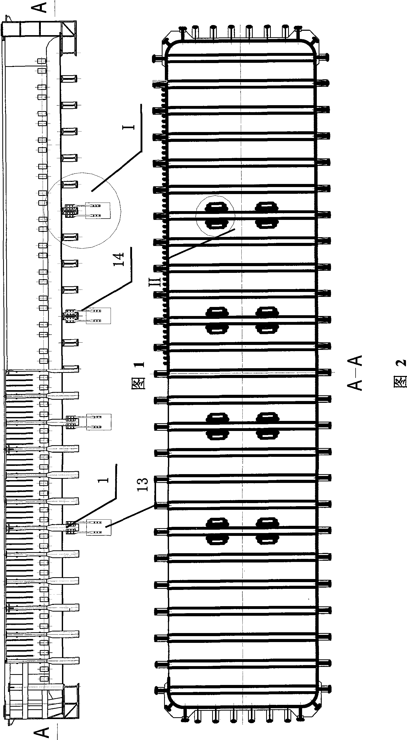
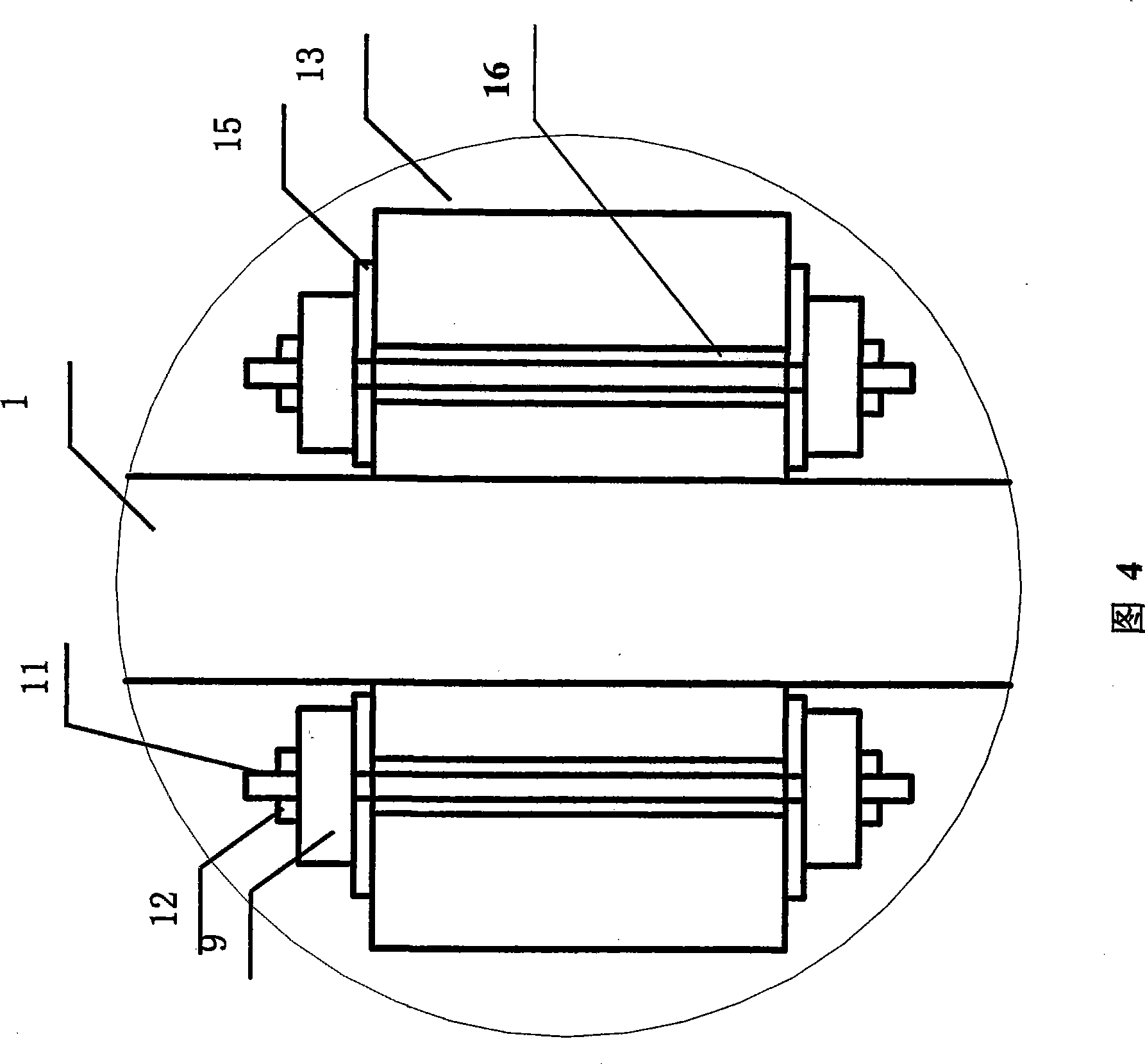
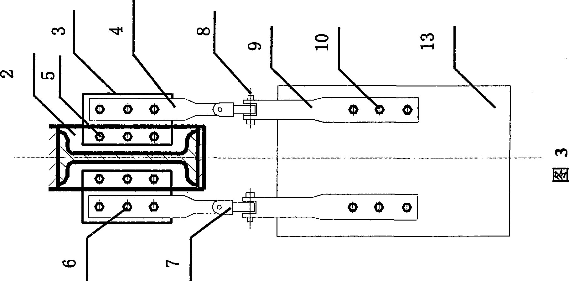
[0036] Embodiment 1: As shown in Fig. 1, Fig. 2, Fig. 3 and Fig. 4, an anti-arch structure at the bottom of the aluminum electrolytic cell, which uses a connecting mechanism 14 to connect the cradle frame 1 of the electrolytic cell to the support pier of the electrolytic cell 13 are connected to prevent the deformation of the upper arch of the cradle frame 1 forcibly. This connecting mechanism 14 mainly contains: upper link 4, lower link 9, fork joint 7, steel plate 2, steel plate 3, bolt nut 5, bolt nut 6, bolt nut 8, bolt nut 10, bolt 11 and nut 12.
specific Embodiment approach
[0037] The specific embodiment: weld steel plate 2 on the cradle frame 1 of electrolyzer, open three bolt holes on steel plate 2, connect with another steel plate 3 by bolt nut 5, steel plate 3 is connected with upper link 4 by bolt nut 6, The upper link 4 and the lower link 9 are connected by a fork joint 7. The advantage of using the fork joint 7 is that the upper link 4 and the lower link 9 can not only rotate back and forth, but also can rotate left and right, so that it is convenient for the cradle frame 1 to connect with the electrolytic The connection between the groove buttresses 13 does not produce rigid constraints, and the fork joint 7 and the lower link 9 are connected by bolts and nuts 8 . The lower link 9 is connected to the electrolytic cell abutment 13 through bolts and nuts 10 , as shown in FIG. 4 , the bolts and nuts 10 are composed of bolts 11 and nuts 12 . The advantage of using bolt connection is that it is convenient for construction and easy to operate. ...
Embodiment 2
[0043] Embodiment 2: as shown in Fig. 5, Fig. 6, Fig. 3 and Fig. 4, the connecting mechanism 14 adopted is the same as that of Embodiment 1, and the implementation mode of the connecting mechanism 14 is also the same, the difference is that this embodiment is in electrolysis On the cradle frame 1 at the bottom of the tank, two connection mechanisms 14 are adopted, which are distributed on the cradle frame 1 near the center line of symmetry of the electrolyzer. The steel plate 2 and another steel plate 3 can also be welded; the steel plate 3 and the upper link 4 are welded; the lower link 9 and the electrolytic cell pier 13 are welded; the fork joint 7 and the lower link 9 The connection is welded.
[0044] In this embodiment, an insulating structure is provided at the bolt joints to insulate the cradle frame 1 of the electrolytic cell from the supporting pier 13 of the electrolytic cell. The insulating structure can adopt any structure that can realize insulation, such as ins...
PUM
 Abstract
Description
Claims
Application Information
 - R&D
- Intellectual Property
- Life Sciences
- Materials
- Tech Scout
- Unparalleled Data Quality
- Higher Quality Content
- 60% Fewer Hallucinations
Browse by: Latest US Patents, China's latest patents, Technical Efficacy Thesaurus, Application Domain, Technology Topic, Popular Technical Reports.
© 2025 PatSnap. All rights reserved.Legal|Privacy policy|Modern Slavery Act Transparency Statement|Sitemap|About US| Contact US: help@patsnap.com


