Sieve tube well completion method under insufficient balance condition and temporary blocking type sieve tube

A screen completion and underbalanced technology, which is applied in the field of oil drilling and cementing, can solve problems such as the complexity of expansion tools, and achieve the effects of avoiding pollution, protecting production layers, and preventing pollution

Active Publication Date: 2009-05-27
BC P INC CHINA NAT PETROLEUM CORP +1
View PDF1 Cites 10 Cited by
  • Summary
  • Abstract
  • Description
  • Claims
  • Application Information

AI Technical Summary

Problems solved by technology

Overcome the disadvantages of complex expansion tools used in the underbalanced well completion method provided by CN1891974A and the need for matching hydraulic equipment

Method used


Image

  • Sieve tube well completion method under insufficient balance condition and temporary blocking type sieve tube
  • Sieve tube well completion method under insufficient balance condition and temporary blocking type sieve tube
  • Sieve tube well completion method under insufficient balance condition and temporary blocking type sieve tube

Examples


Embodiment 1

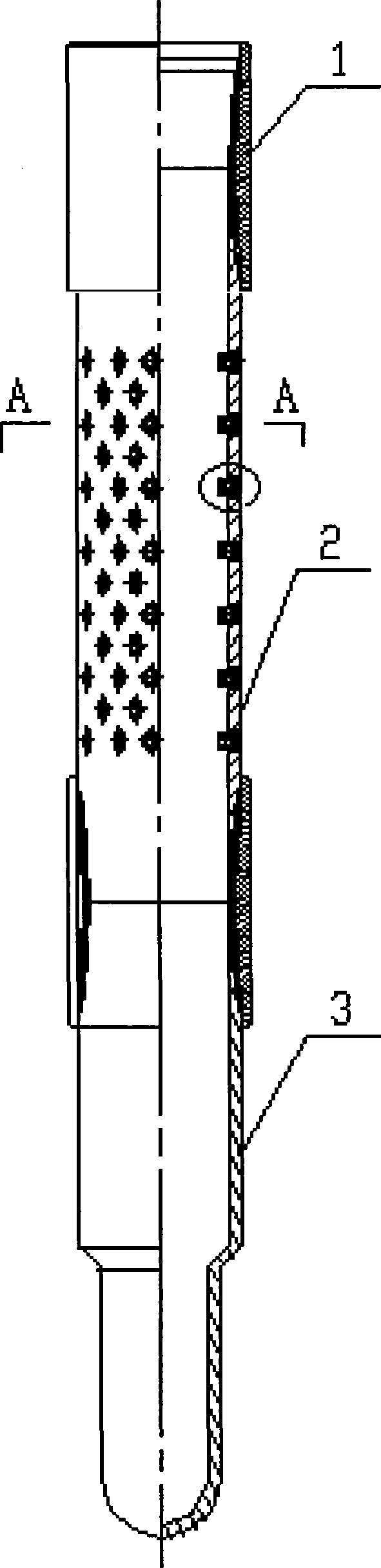
[0025] Embodiment 1: With a 5000-meter-deep oil well that adopts the underbalanced drilling method to complete, the well section above 3500 meters has 7 "technical casing cementing. It is necessary to lower a section of 100-meter-long 5 " temporary drilling at the lowermost end of the oil well. Taking the plugged screen as an example, the screen completion method under the under-balanced condition is further described in detail.

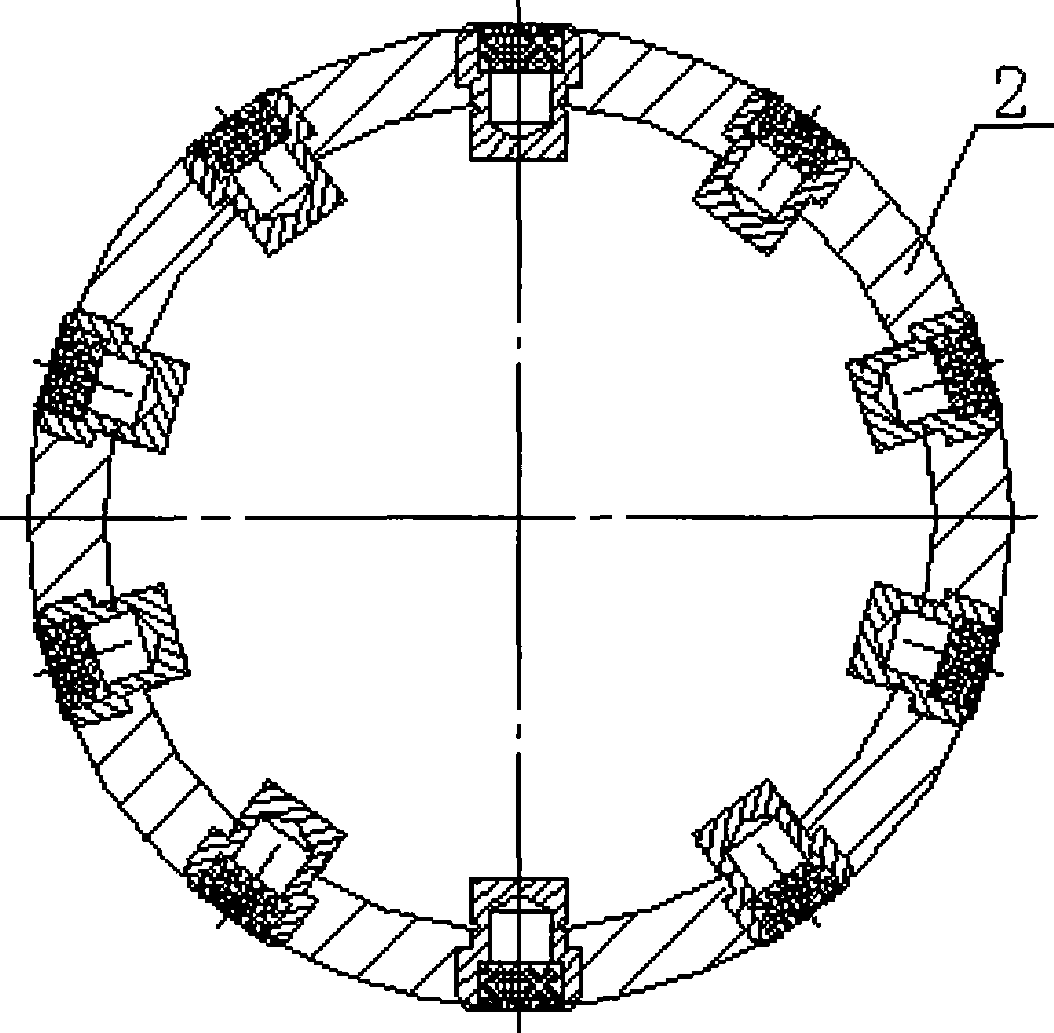
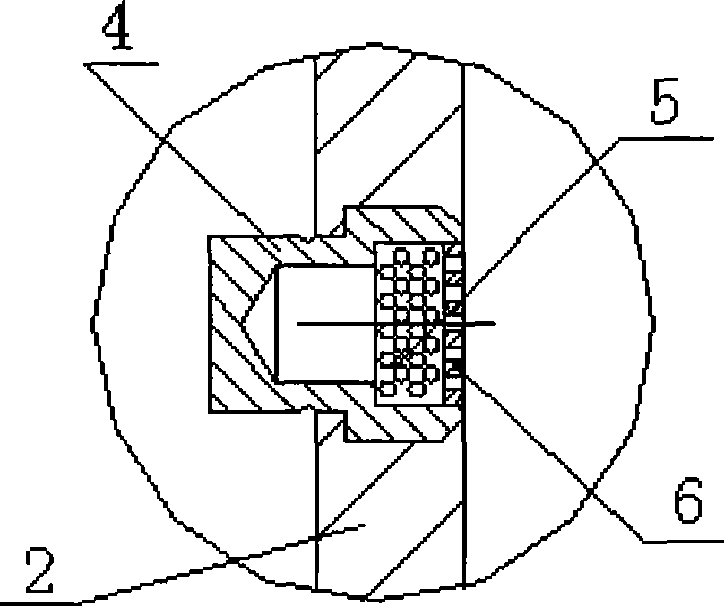
[0026] Connect the guide shoe 3 with the 5″ temporary plugging screen with coupling 1, the upper part of the temporary plugging screen is 100 meters long, the upper part of the temporary plugging screen is connected to the liner hanger, and the upper part of the liner hanger is connected to the drill pipe. During the process, the plugging of the temporary plugging screen can seal off the pressure in the well, so that the mud cannot enter the temporary plugging screen, so as to achieve underbalanced running.Refer to figure 1 . The base pipe 2 of each...

Embodiment 2

[0030] Embodiment 2: Embodiment 2 is basically the same as Embodiment 1. The difference is: when the casing string is lowered into the wellbore, the top of the casing is connected to the liner hanger, and the casing string with the temporary plugging screen is suspended on the inner wall of the upper layer of casing by the liner hanger . The specific difference is: when the connecting length of the lower casing string reaches 1500 meters, the upper part is connected with a 7″×5″ liner hanger. The upper part of the 7″×5″ liner hanger connects the drill pipe all the way to the wellhead. Use the drill pipe to hang the liner hanger on the inner wall of the lower end of the 7" technical casing. The process and method of liner hanger have been used for decades and can be completed by those skilled in the art, and will not be described in detail.

Embodiment 3

[0031] Embodiment 3: Embodiment 3 is basically the same as Embodiment 1. The difference is that when the casing string is lowered into the wellbore, the top of the casing is used to connect the expansion tube, and the expansion tool is used to seal the expansion tube on the inner wall of the upper layer of casing. The specific difference is: when the connection length of the lower casing string reaches 1500 meters, the upper part is connected with a 1.3-meter 5" expansion pipe and expansion tool. The upper part of the 5" expansion pipe is connected with the drill pipe all the way to the wellhead. Then utilize the expansion tool to hang the expansion tube seat on the lower end inner wall of the 7 "technical sleeve. The process and method of expansion tube expansion sealing (seat hanging) have been used for decades, and those skilled in the art can complete it, so it will not be described in detail.


PUM


Abstract

The invention relates to a well completion method through a sieve tube under the underbalanced condition, which is applied to the field of oil drilling well cementation technology. The well completion method is characterized in that a sleeve column with a temporary plugging type sieve tube descends to a well; the sleeve column has a structure that the sleeve column is connected with a guide shoe, the temporary plugging type sieve tube and a sleeve from bottom to top; a drilling and milling tool descends to the sleeve column through a drill rod; and finally, the part of the plugging blind end face of the temporary plugging type sieve tube protruding the inner wall of a base tube is milled or cut and cleaned through the drilling and milling tool. The method has the advantages that with the adoption of the sleeve column with the temporary plugging type sieve tube, when the sleeve is lowered, annular air of the inside and the outside of a sieve tube column are not communicated so as to protect a production layer and avoid pollution on the production layer. After the lowering of the sleeve is completed, the part of the plugging blind end face protruding the inner wall of the base tube is removed through the drilling and milling tool to unblock the plugging so that oil gas can enter the sleeve column. The method solves the difficult technical problem of using the sieve tube to realize the underbalanced well completion after the underbalanced well drilling.

Description

Technical field: [0001] The invention relates to the technical field of oil drilling and well cementing, in particular to a screen tube completion construction method, which is a screen tube completion method under an under-balanced condition. Background technique: [0002] As an effective means to reduce reservoir damage, improve oil and gas well productivity, and solve problems such as low drilling rate, lost circulation, and differential pressure sticking in conventional drilling technology, underbalanced drilling technology has attracted more and more attention from the petroleum industry. More importantly, underbalanced drilling technology is conducive to reducing the cost of oil and gas exploration and development, and can effectively and timely discover and protect oil and gas reservoirs, which has become a hot spot in the development of drilling technology. The underbalanced completion technology is an extension of the underbalanced drilling technology. It is a new w...

Claims


Application Information

Patent Timeline
Patent Type & Authority Applications(China)
IPC IPC(8): E21B43/10
Inventor 任荣权王辉王建利尹洪伟于永亮曹川耿莉
Owner BC P INC CHINA NAT PETROLEUM CORP
Why Eureka
Try Eureka