Seal structure and seal method of engine camshaft cover

A technology of camshaft cover and sealing structure, which is applied to the sealing device of the engine, engine components, machines/engines, etc. It can solve the problems that affect the performance of the product, have many restrictions, and are difficult to meet the requirements.

Inactive Publication Date: 2009-05-27
CHERY AUTOMOBILE CO LTD
View PDF0 Cites 11 Cited by
  • Summary
  • Abstract
  • Description
  • Claims
  • Application Information

AI Technical Summary

Problems solved by technology

Because this sealing method has high requirements on the surface roughness, flatness, bolt pressing force and pressure uniformity of the two joint surfaces, due to many restricti

Method used


Image

  • Seal structure and seal method of engine camshaft cover
  • Seal structure and seal method of engine camshaft cover
  • Seal structure and seal method of engine camshaft cover

Examples


Embodiment Construction

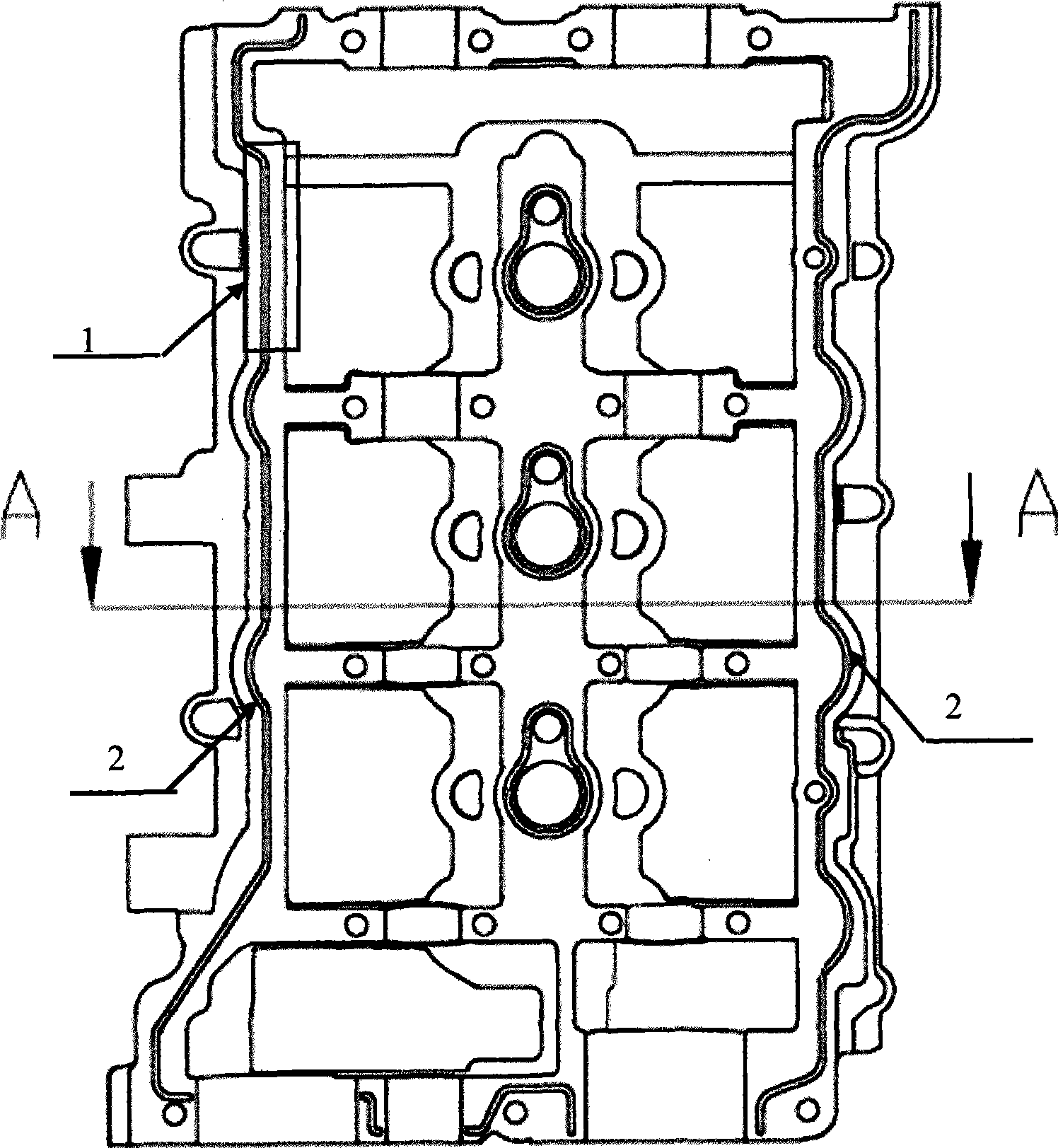
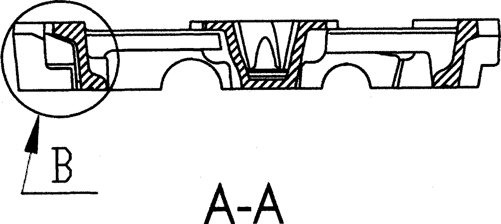
[0010] Such as figure 1 and figure 2 , the sealing surface 1 of the camshaft cover is engraved with a rubber storage tank 2, the rubber storage tank is engraved or reserved during casting, the rubber storage tank is filled with silica gel, and the camshaft cover is pressed tightly on the camshaft cover with bolts on the cylinder head.

[0011] Slots can play two roles. First, due to the relatively high viscosity of silica gel, if the silicone seal is used directly without grooves, after the bolts compress the camshaft cover, more silica gel will remain between the sealing surfaces and affect the camshaft hole. The roundness of the shaft hole, most of the silica gel remains in the groove after the groove, which can reduce the impact of the silica gel on the roundness of the shaft hole. Second, after the silica gel is cured, it is equivalent to adding an elastic gasket to the groove, which is beneficial to the sealing of the camshaft cover and the cylinder head.


PUM


Abstract

The invention relates to a sealing structure of a camshaft cover and a cylinder head and a sealing method thereof. In the sealing structure, a sealing face (1) of the camshaft cover is provided with a gel storage slot (2); silica gel is coated in the gel storage slot; and the camshaft cover is tightly pressed on the cylinder cover by a bolt. With sealing by notch and silica gel, the requirement on roughness and planeness of the sealing face is not so high, thereby reducing the requirement and sealing condition on the sealing face, reducing manufacturing cost, and realizing excellent and lasting sealing.

Description

technical field [0001] The invention relates to an engine camshaft cover, in particular to a sealing structure and a sealing method of a camshaft cover and a cylinder head. Background technique [0002] Usually, the sealing of the integral camshaft cover and the cylinder head is to apply anaerobic adhesive on the joint surface, and then tighten it with bolts to form a sealing band. After the anaerobic adhesive solidifies between the sealing bands, it forms a seal on both sides. Because this sealing method has high requirements on the surface roughness, flatness, bolt pressing force, and pressure uniformity of the two joint surfaces, due to many restrictive conditions, it is difficult to meet the requirements in actual production. Therefore, it is easy to produce leakage of lubricating oil, which affects the performance of the product. Contents of the invention [0003] The purpose of the present invention is to overcome the above-mentioned problems, realize the good and l...

Claims


Application Information

Patent Timeline
IPC IPC(8): F01L1/053F02F11/00
Inventor 刘正东姜博琦
Owner CHERY AUTOMOBILE CO LTD
Why Eureka
Try Eureka