Light selective absorbing coating and its process

a technology of selective absorbing coating and light absorption, which is applied in the direction of synthetic resin layered products, instruments, transportation and packaging, etc., can solve the problems of high raw material cost, inability to obtain homogenous film materials, and the coating system is only suitable for vacuum environments, so as to prevent the interdiffusion of metal atoms and enhance the light absorption ratio of the light absorption system

Inactive Publication Date: 2010-02-11
SHENZHEN COMMONPRAISE SOLAR
View PDF7 Cites 22 Cited by
  • Summary
  • Abstract
  • Description
  • Claims
  • Application Information

AI Technical Summary

Benefits of technology

[0034]The object of the present invention is to provide a light selective absorbing coating and a production process thereof. The absorbing coating is easily controlled in the production process. Preferably the absorbing coating is suitable for using at high temperature in vacuum or air. Moreover, the light selective absorbing layer has a solar absorptance α of greater than 0.92.
[0041]Stainless steels are all iron chromium alloys and can be classified based on the structure at room temperature, including martensite type, austenic type, ferrite and dual-phase stainless steel. Since stainless steel has excellent properties of corrosion resistance, workability, compatibility and strong toughness in very broad temperature range, it has been widely applied in heavy industry, light industry, articles of life and building and decoration fields.
[0043]The stainless property and corrosion resistance of iron chromium alloy materials are attributed to chromium-rich oxide films (passive films) formed on the surface thereof. Chromium oxide of compact structure prevents diffusion of oxygen, thereby preventing oxidation of iron in the crystal cell of alloy, and greatly enhancing the capacity of anti-high temperature and anti-oxidation of iron alloy. Alloying elements endow further advantages of the prepared absorbing coating, for example, nickel and aluminum also have similar actions to reduce diffusion of iron ion and oxygen ion, nickel in relatively high content and iron chromium constitute austenic stainless steel. Austenic stainless steel having no magnetic property is suitable for application in magnetron sputtering technology. Micro particles of small amount of rare earth metal oxides such as Y2O3 can further strengthen alloys and effectively prevent the growth of high temperature crystal particles so as to prevent embrittlement of film. Said alloying elements are preferably selected from one or more of nickel, aluminum, molybdenum and yttrium.
[0044]It is surprising that the production process of metal-medium composite material films with vacuum deposition technology is easily operated and controlled when using iron chromium alloy as a metal raw material, a mixed gas of oxygen and nitrogen-containing gas as reactive gas. Hence, a composite material film of uniform optical constants can be obtained, by which the optical constants vary with slight regulation of the flow rate of reactive gas. In addition, said composite material film not only has excellent anti-high temperature property and anti-oxidation property, but also when it is used as light selective absorbing coating, the constituted light selective absorbing coating layer system has an actual solar absorptance αp more than 0.93. Therefore, metal-medium composite material film of iron chromium alloy can become a selection of light selective absorbing coating material. However, more prominent features lie in that the film can work at high temperature in vacuum or under air atmosphere. Moreover, stainless steel materials, as an industrial raw material widely used in the market, can be commercially available various types of stainless steel plates, tubes, and the like, without needing special production. As compared with other metal raw materials for producing light selective absorbing coatings in the prior arts, the present invention greatly reduces the cost of raw materials of solar energy selective absorbing coating system. For example, the price of the stainless steel materials is only from 1 / 10 to 1 / 20 of that of chromium nickel alloy used generally in present solar flat plate selective absorbing coating system.
[0053]In the present invention, a buffer layer is optionally used, which consists of metal materials, preferably copper-based or molybdenum-based alloys. The buffer layer is for preventing the interdiffusion of metal atoms and migration of particles between the high infrared reflective substrate layer and the absorbing layer. The buffer layer has a thickness of about 20 nm.

Problems solved by technology

However, too large power causes the reactive unstable, so that homogeneous film materials cannot be obtained.
There are numerous possibilities for different metals to combine different reactive gases, since the composition of absorbing layer materials successfully obtained in practice and its relevant principle lack theoretical explanation, random screenings are carried out in seeking new materials of absorbing layers in the art.
In the prior art, elementary metals such as titanium, chromium, or alloys such as nickel chromium alloy, useful for producing absorbing layers are required to be customized, therefore the cost of raw materials is high.
The coating system is only suitable for use in vacuum environments.
However, micro particles of IVA group metal are poor in corrosion resistance and anti-oxidation property.

Method used


Image

  • Light selective absorbing coating and its process
  • Light selective absorbing coating and its process
  • Light selective absorbing coating and its process

Examples


example 1

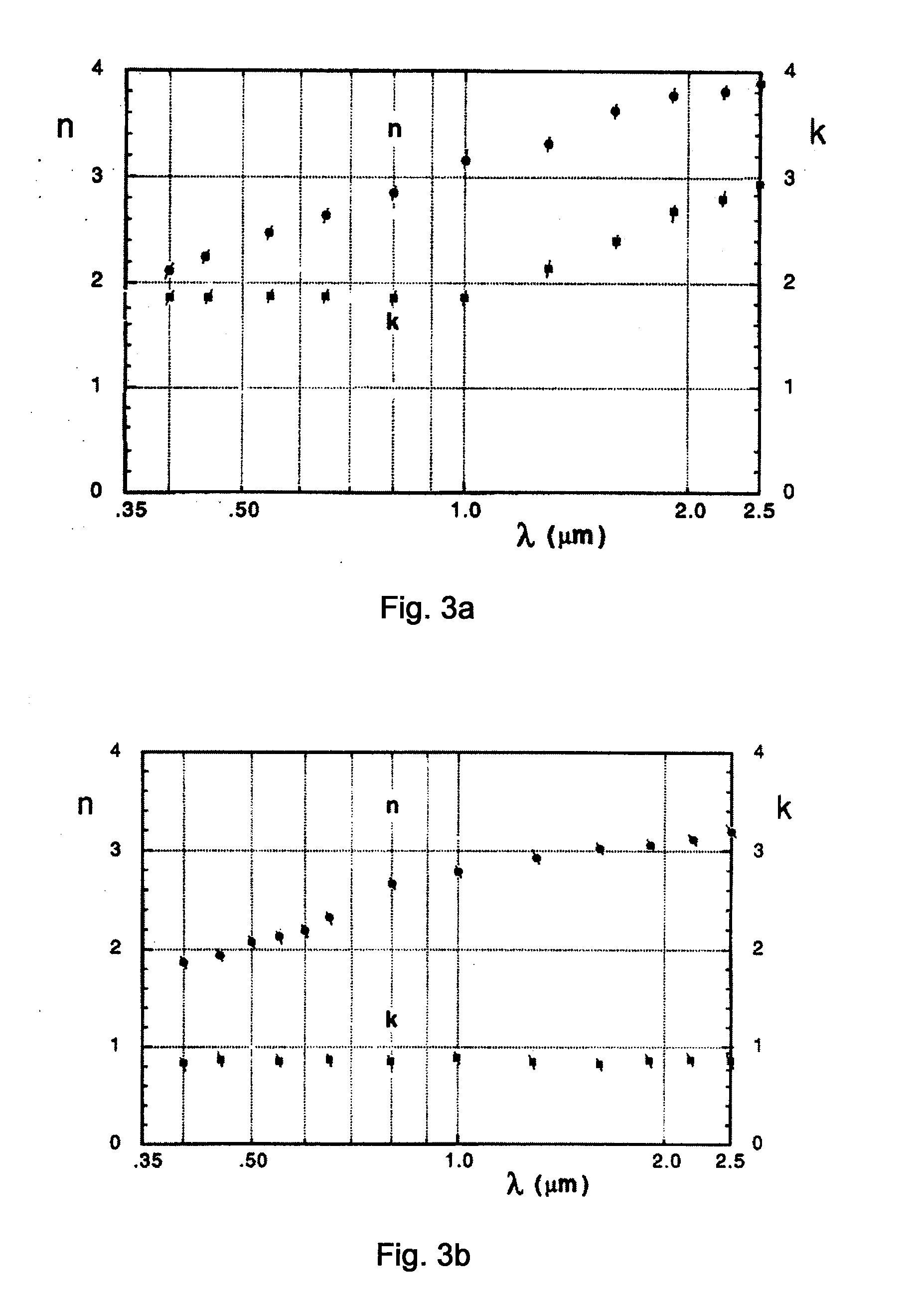
Magnetron sputtering Deposition of AISI 316L (00Cr17Ni14Mo2) Oxynitride Composite Material Film at Low Power and Measurement and Calculation of Optical Constants Thereof

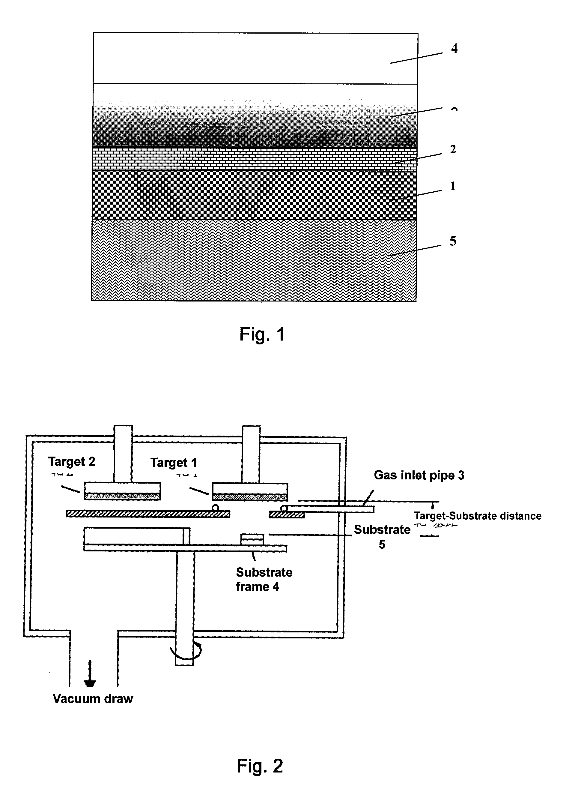
[0081]In vacuum chamber of planar magnetron sputtering coating machine as shown in FIG. 2, the magnetron sputtering chamber had a volume of about 0.1 m3, in which AISI 316L (00Cr17Ni14Mo2) iron chromium alloy target 1 was disposed at the upper part therein, with the target facing downward; a glass substrate 5 with a dimension of 25 mm×38 mm×1 mm was mounted in the substrate frame 4, the distance between the target and the substrate was 70 mm; a gas inlet pipe 3 was mounted about the target, a gas or a mixed gas was injected, respectively; the sputtering chamber wall and the substrate were used as anode isoelectric potential and grounded; permanent magnetic circuit was used for two plane targets, a magnetic field vertical to electric field was generated on the surface of target cathode to constitute electric and magne...

example 2

Magnetron Sputtering Deposition of AISI 316L (00Cr17Ni14Mo2) Oxynitride Composite Material Film at Large Power and Measurement and Calculation of Optical Constants Thereof

[0085]Under the conditions of the equipments as shown in FIG. 2 identical to those in Example 1, the direct current sputtering power was set at about 5 kW. The injection rate of gases was tried to increase. After conventional adjustments, a composite material film having closest optical constants to that of Example 1 was obtained under following technological parameters.

[0086]A flow rate of 35 sccm of Ar was injected through the gas inlet pipe 3 into the sputtering chamber to make the pressure of the sputtering chamber be 0.4 Pa, and 150 sccm of nitrogen gas and 15 sccm of oxygen gas were injected into the chamber. The direct current sputtering power was 5.17 kW. The sputtering was carried out for 40 seconds. The thickness of film was measured by means of α-Step instrument. FeCr17Ni14Mo2-N-O (1) film with a deposit...

example 3

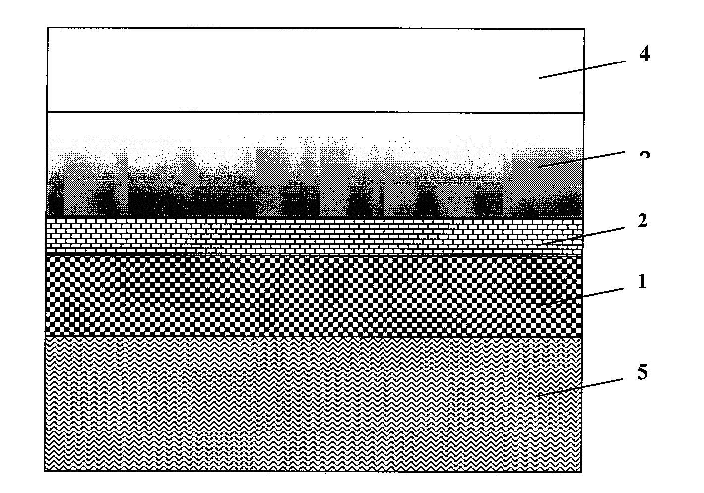
Deposition of FeCr17Ni14Mo2-N-O / SnNO Solar Energy Selective Absorbing Coating System on the Substrate to Prepare Solar Energy Heat Collecting Element

[0090]Copper sheet as the substrate 5 was mounted on the substrate frame of planar magnetron sputtering plating machine as shown above in FIG. 2. The magnetron sputtering chamber had a volume of about 0.1 m3, in which AISI 316L (00Cr17Ni14Mo2) alloy target 1 and Sn target 2 were installed at the upper part therein, with the targets facing downward. The distance between the targets and the substrate was 70 mm. The magnetron sputtering chamber was vacuumed into low vacuum and then high vacuum to 10−3 Pa by using a mechanical pump. The conductance between the sputtering chamber and the high vacuum pump was regulated by a throttle valve.

[0091]A flow rate of 35 sccm of Ar was injected through the gas inlet pipe 3 into the sputtering chamber to make the pressure of the sputtering chamber be 0.4 Pa, and 150 sccm of nitrogen gas and 15 sccm of...


PUM

PropertyMeasurementUnit
mol %aaaaaaaaaa
total thicknessaaaaaaaaaa

Abstract

The present invention relates to a light selective absorbing coating and a production process thereof. The light selective absorbing coating consists of a composite material film deposited by reaction of iron chromium alloy and a non-metal gas with vacuum deposition technology. Said non-metal gas comprises gases of nitrogen and oxygen elements. The present invention also relates to a solar energy heat collecting element or solar energy selective absorbing coating system comprising said light selective absorbing coating and a production process thereof. The present invention further relates to use of said composite material film as a light selective absorbing coating of a solar energy heat collecting element or of a solar energy selective absorbing coating system.

Description

TECHNICAL FIELD[0001]The present invention relates to a light selective absorbing coating and a production process thereof. The light selective absorbing coating consists of a composite material film deposited by reaction of iron chromium alloy and a non-metal gas with vacuum deposition technology. Said non-metal gas is preferably a gas comprising nitrogen and oxygen elements. The present invention also relates to a solar energy heat collecting element or solar energy selective absorbing coating system comprising said light selective absorbing coating and a production process thereof. The present invention further relates to use of said composite material films as a light selective absorbing coating of a solar energy heat collecting element or of a solar energy selective absorbing coating system.BACKGROUND ART[0002]Light selective absorbing coatings are core functional parts in light absorptive systems for absorbing light energy. They are usually applied in solar energy heat collect...

Claims


Application Information

Patent Timeline
Patent Type & Authority Applications(United States)
IPC IPC(8): B32B15/04C09D1/00B05D3/00C23C14/32
CPCC23C14/0676C23C14/0688Y10T428/265Y02E10/40Y10T428/24975F24J2/487F24S70/225F24S70/25
Inventor YIN, ZHIQIANG
Owner SHENZHEN COMMONPRAISE SOLAR
Why Eureka
Try Eureka