
Method for controlling an internal combustion engine

A technology for internal combustion engines and regulators, which is applied to the cooling of internal combustion piston engines, combustion engines, and engines. It can solve problems such as high temperature rise of charge air coolers, increased loads of internal combustion engine components, and reduced life expectancy. Stabilize the regulating circuit Effect

Inactive Publication Date: 2009-05-27
MTU MOTOREN & TURBINEN UNION FRIEDRICHSHAFEN GMBH
View PDF2 Cites 2 Cited by
  • Summary
  • Abstract
  • Description
  • Claims
  • Application Information

AI Technical Summary

Problems solved by technology

In the case of rapid load cut-ins, e.g. during rapid acceleration, the temperature may rise too high mainly in the charge air cooler due to the coolant being too hot
It causes an increased load on the components of the internal combustion engine and can cause a reduction in service life

Method used

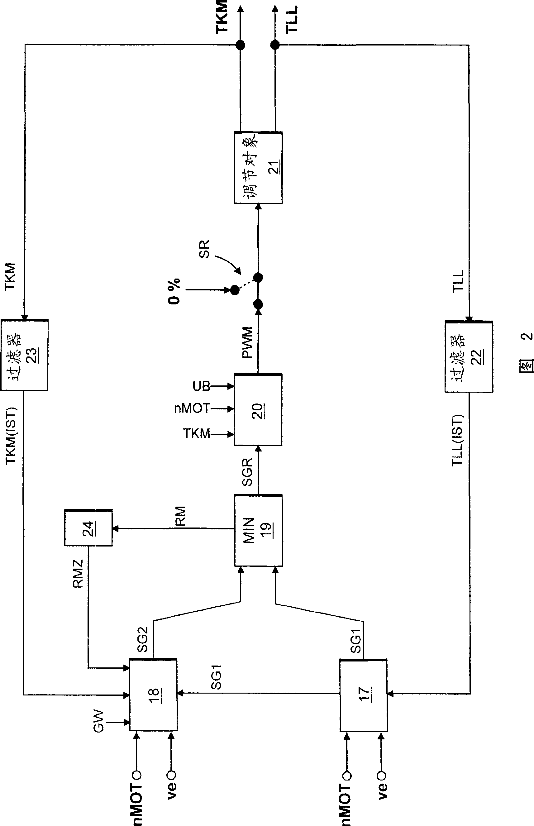
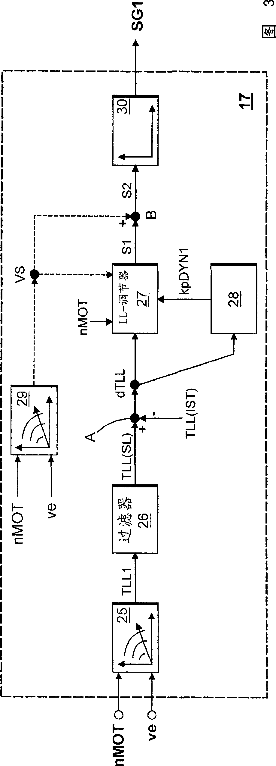

Image

  • Method for controlling an internal combustion engine
  • Method for controlling an internal combustion engine
  • Method for controlling an internal combustion engine

Examples


Embodiment Construction

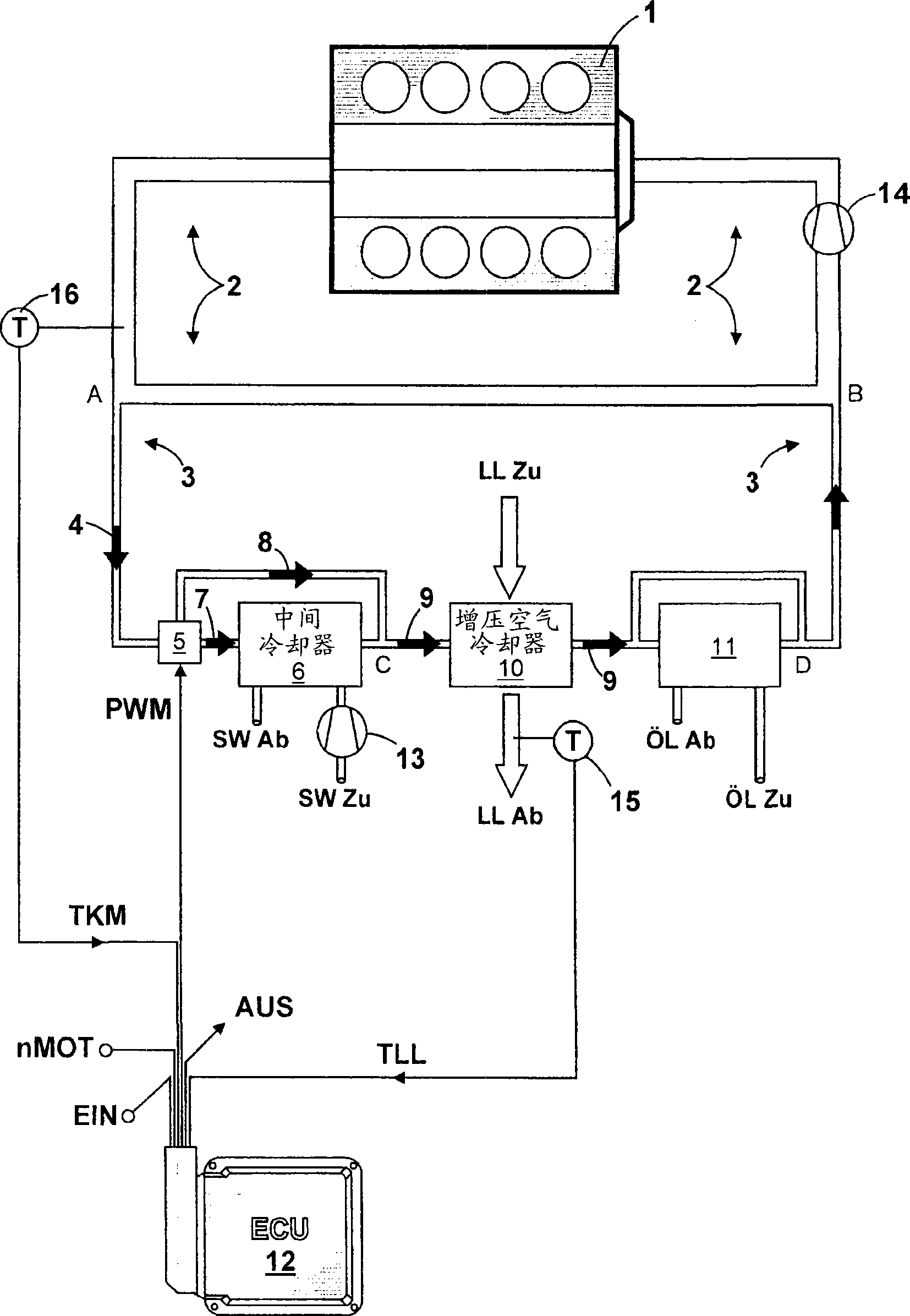
[0018] figure 1 A system diagram is shown. The cooling circuit for cooling internal combustion engine 1 comprises a high-temperature circuit 2 with a coolant pump 14 and a low-temperature circuit 3 . The low-temperature circuit 3 branches off from the high-temperature circuit 2 at point A and joins again at point B into the high-temperature circuit 2 . The coolant flows in the high-temperature circuit 2 and in the low-temperature circuit 3 are regulated via throttling points (not shown) in the high-temperature circuit 2 . The coolant flow in the low-temperature circuit 3 after the branching point (position A) out of the high-temperature circuit 2 is designated as coolant flow 4 in the figure. A combined characteristic curve thermostat valve 5 , an intercooler 6 with a bypass line, a charge air cooler 10 and a lubricating oil heat exchanger 11 with a bypass line are arranged in series in the low-temperature circuit 3 . The coolant flow 4 is divided into an intercooler coolan...


PUM


Abstract

The invention concerns a method for automatically controlling an internal combustion engine, wherein, in a first controller mode (RM1), a charge air temperature controller 27 is set as dominant for a map-controlled thermostatic valve 5, and, in a second controller mode (RM2), a coolant temperature limit controller 33 is set as dominant for the map-controlled thermostatic valve 5. Upstream of a recooler, a coolant flow 4 is divided into a recooler coolant flow 7 and a bypass coolant flow 8 as a function of the position of the map-controlled thermostatic valve 5. Downstream of the recooler, the temperature 9 of the charge air cooler coolant flow is determined from the combined fractions of the recooler coolant flow 7 and the bypass coolant flow 8 to control the charge air temperature (TLL) or to control the coolant temperature (TKM).

Description

technical field [0001] The invention relates to a method for regulating an internal combustion engine, in which in a first regulator mode a charge air temperature regulator is set as the leading regulator for a combined characteristic curve thermostat valve and in a second regulator mode a coolant The temperature limiting regulator is set as the leading regulator for the combined characteristic curve thermostat valve. In addition, depending on the position of the combined characteristic curve thermostat valve, the coolant flow is divided into intercooler coolant flow and bypass coolant flow before the intercooler and through intercooler coolant flow and bypass coolant after the intercooler The combined proportion of the flows determines the temperature of the intercooler coolant flow in order to regulate the charge air temperature or to regulate the coolant temperature. Background technique [0002] A coolant circuit for an internal combustion engine is known from the magaz...

Claims


Application Information

Patent Timeline
Patent Type & Authority Applications(China)
IPC IPC(8): F02B29/04F02D45/00F01P7/14
CPCY02T10/146F01P2025/60F02B29/0443F01P2060/02F01P2025/64F02B29/0493F01P2060/04Y02T10/12
Inventor A·德尔克
Owner MTU MOTOREN & TURBINEN UNION FRIEDRICHSHAFEN GMBH
Learn More