Electric fan

A technology of electric fans and fan blades, which is applied in the field of new electric fans, can solve problems such as time-consuming, unfavorable market competition, and complicated installation process, and achieve the effects of increasing air volume, improving the beauty of life, and reducing transportation costs

Inactive Publication Date: 2009-05-27
TUNG ELECTRIC +1
View PDF2 Cites 4 Cited by
  • Summary
  • Abstract
  • Description
  • Claims
  • Application Information

AI Technical Summary

Problems solved by technology

It is necessary to combine the ribs of the upper cover with the barbs of the base ring, and then fasten the three with screws, nuts a

Method used


Image

  • Electric fan
  • Electric fan
  • Electric fan

Examples


Embodiment 1

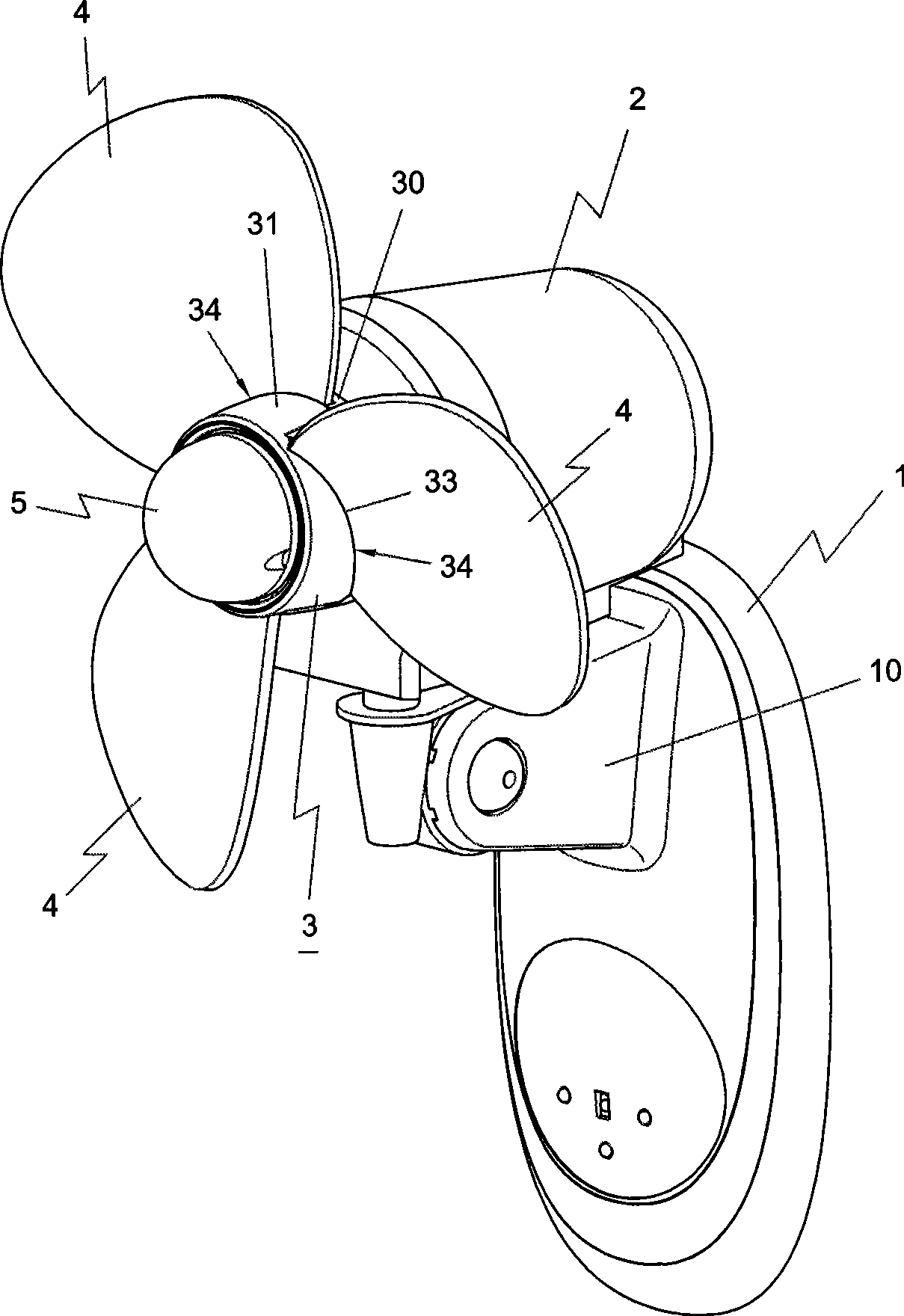
[0042] Such as figure 1 and 2 Shown, be embodiment 1 of electric fan of the present invention, embodiment 1 comprises:

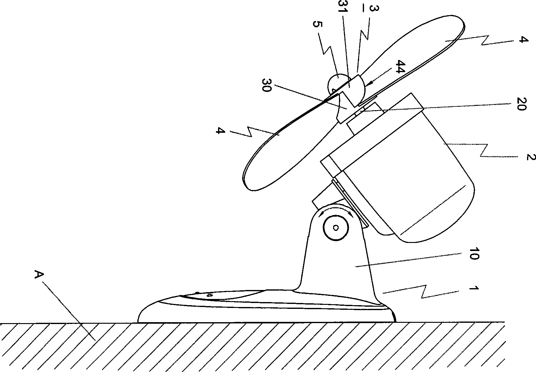
[0043] Base 1. The base 1 can be hung on the wall A or stand on the ground or on a table. A connecting seat 10 is provided on the base 1 to set the motor unit 2.

[0044] The motor unit 2, the motor unit 2 is located on the connection seat 10 of the aforementioned base 1, so that the motor unit 2 can adjust the angle up and down, as figure 2 As indicated by the R arrow, the motor unit 2 is provided with a mandrel 20 .

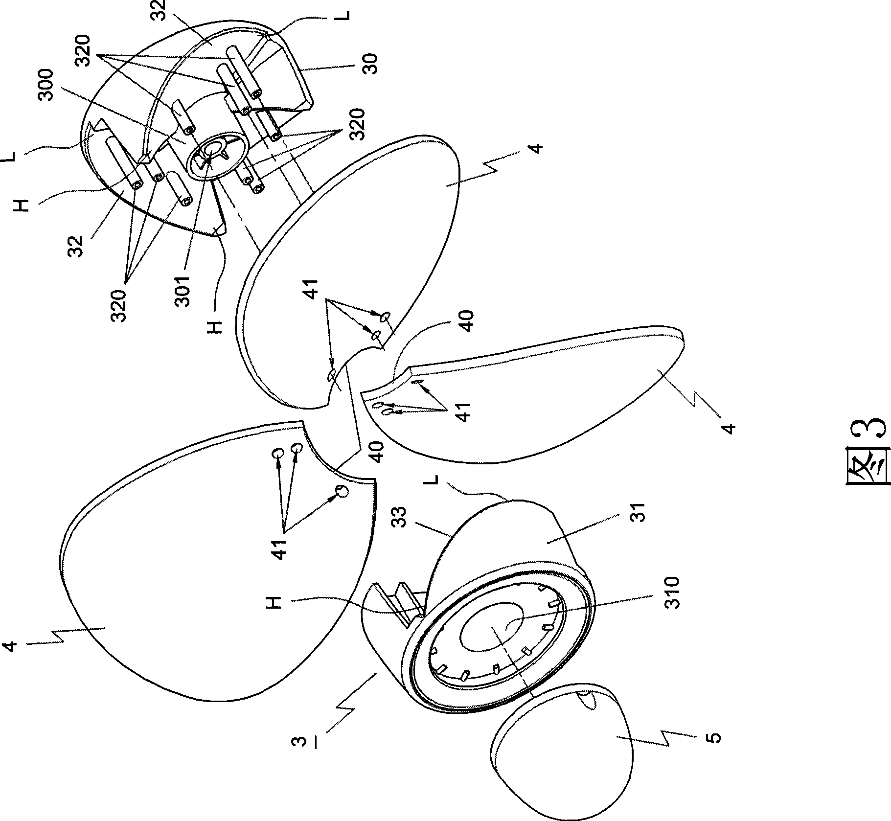
[0045] The blade seat 3, as shown in Figure 3, is provided with a first assembly 30 and a second assembly 31 corresponding to each other, the first assembly 30 is provided with a joint seat 300, the joint seat 300 is also provided with a shaft hole 301, and the second assembly 31 is provided with a joint Set 310, another example Figure 4 As shown, a plurality of curved surfaces 32, 33 are respectively provided on the first component 30 ...

Embodiment 2

[0049] Such as Figure 11 Shown, be embodiment 2 of electric fan of the present invention, embodiment 2 comprises:

[0050] The structures of the base 1 , the motor unit 2 and the fan blade 4 are the same as those of the base 1 , the motor unit 2 and the fan blade 4 in the first embodiment.

[0051] The blade seat 6 of the second embodiment is provided with a first assembly 60 and a second assembly 61 corresponding to each other, the first assembly 60 is provided with a joint seat 600, the joint seat 600 is also provided with a shaft hole 601, and the second assembly 61 is provided with a joint sleeve 610, a plurality of curved surfaces 62, 63 are respectively provided on the first component 60 and the second component 61 (this can refer to Figure 4 ), the curved surfaces 62, 63 of the first component 60 and the second component 61 are in a symmetrical shape, and form a relatively symmetrical side (refer to Figure 11 H point), gradually lowering to one side (see Figure 11 ...


PUM


Abstract

The invention discloses an electric fan, which comprises a base, a motor machine set, fan blade seats and fan blades, wherein the base is provided with a connecting seat and the motor machine set; the motor machine set is arranged on the connecting seat of the base and provided with a mandrel; the fan blade seats are provided with first components and second components which are corresponding and provided with combination seats and combination sleeves respectively, the combination seats are provided with shaft holes, the first components and the second components are provided with a plurality of curved surfaces respectively, the curved surfaces of the second components are of a corresponding shape, the curved surfaces of the first components are provided with a plurality of protruded pillars, and the first components and the second components form fan blade accommodating grooves when the first components and the second components are mutually combined; the fan blades are provided with a plurality of the fan blade accommodating grooves matched with a plurality of the fan blade seats, and the fan blades are made of a foaming or flexible material into a plane shape and are provided with grooves and a plurality of holes; and the first components and the second components of the fan blade seats are combined with the fan blades to form the electric fan. The electric fan does not need to arrange a safety net, namely, the electric fan has safety design, can save manufacturing cost, can not resist air-out effect and improve air output.

Description

technical field [0001] The invention relates to an electric fan, in particular to a new type of electric fan whose fan blades are made of foaming or slightly soft materials that will not hurt even if they are touched. Background technique [0002] The fan blades currently on the market are all made of acrylonitrile-butadiene-styrene copolymer (ABS) rigid plastic materials. The fan blades made of the above-mentioned rigid plastic materials are hard to use When the fan blade is rotating, once the user touches the fan blade accidentally, it will cause injury. Therefore, the electric fans currently on the market all have a safety net. Although the safety net isolates the fan blades from the outside world, it often happens that users, especially children, reach into the safety net and are injured by the rotating fan blades. Incident, therefore, some electric fan manufacturers and relevant safety regulations require that the mesh of the safety net be reduced, which will affect th...

Claims


Application Information

Patent Timeline
IPC IPC(8): F04D25/08F04D29/38F04D29/02F04D29/66
Inventor 史瑞斌
Owner TUNG ELECTRIC
Why Eureka
Try Eureka