
Heat acoustic refrigerating device based on oscillation flow hot pipe

A technology of oscillating flow heat pipe and thermoacoustic refrigeration, which is applied in refrigerators, refrigeration and liquefaction, lighting and heating equipment, etc., can solve the problems of low refrigeration efficiency and low heat exchange efficiency of heat exchangers, and achieves low cost and large promotion. The effect of value, simple structure

Inactive Publication Date: 2009-05-27
SHAN DONG TIAN LI DRYING EQUIP
View PDF0 Cites 3 Cited by
  • Summary
  • Abstract
  • Description
  • Claims
  • Application Information

AI Technical Summary

Problems solved by technology

However, the heat exchange efficiency of water-cooled heat exchangers commonly used in thermoacoustic refrigerators is not high, resulting in low overall cooling efficiency. Therefore, it is particularly important to find a heat exchanger with higher heat exchange efficiency.

Method used


Image

  • Heat acoustic refrigerating device based on oscillation flow hot pipe
  • Heat acoustic refrigerating device based on oscillation flow hot pipe

Examples


Embodiment Construction

[0019] The present invention will be further described below in conjunction with the accompanying drawings and embodiments.

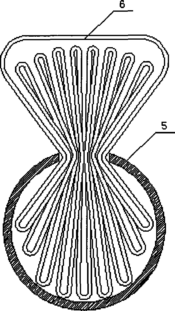
[0020] figure 1 Among them, the present invention includes a resonant cavity 5 filled with gas, a parallel plate stack 3 placed in the resonant cavity 5 , a hot end heat exchange device 2 , a cold end heat exchange device 4 and an acoustic wave generator 1 .

[0021] Both the hot end heat exchange device 2 and the cold end heat exchange device 4 are composed of a group of oscillating flow heat pipes 6, which are arranged orthogonally to the resonant cavity 5. The oscillating flow heat pipes 6 are serpentine loops formed by bending and welding capillary tubes. There is a closed interface on the thin tube, which is used for vacuuming and filling with working fluid.

[0022] Oscillating flow heat pipe: According to the specific heat exchange requirements, select a suitable metal thin tube (the metal tube is easy to process and suitable as a heat exchange ...


PUM


Abstract

The invention relates to a thermoacoustic refrigeration device based on an oscillating-flow heat pipe, which solves problems in prior art of low whole refrigeration efficiency due to low heat conversion efficiency. The invention is provided with higher heat conversion efficiency, thereby improving refrigeration coefficient of the thermoacoustic refrigeration device. The structure of the thermoacoustic refrigeration device comprises a oscillating cavity in which a cold end heat conversion device and a hot end heat conversion device are provided, a pack is provided between the two heat conversion devices, and the cold end heat conversion device and the hot end heat conversion device are respective a set of oscillating-flow heat pipe.

Description

technical field [0001] The invention relates to a thermoacoustic refrigeration device based on an oscillating flow heat pipe. Background technique [0002] For a thermoacoustic refrigeration device, the plate stack is the core component, and the thermoacoustic cooling effect occurs in the plate stack. High and low temperature heat exchangers are respectively placed at the cold and hot ends of the plate stack for heat exchange. The main function of the acoustic wave generator is to maintain the standing wave in the resonant cavity. Under the action of sound waves, the gas oscillates in the plate stack, compressing and expanding periodically. Under the action of compression and expansion of sound waves, an average temperature gradient along the axial direction of the plate stack is formed. At the same time, assuming that the gas is a non-viscous ideal gas, if the medium undergoing acoustic vibration is provided with energy when it is the densest, and By drawing energy from ...

Claims


Application Information

Patent Timeline
IPC IPC(8): F25B23/00
Inventor 李选友史勇春高玲柴本银原成泽刘登瀛蒋斌董宪华
Owner SHAN DONG TIAN LI DRYING EQUIP
Learn More